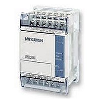
FX1S-30MR-ES/UL MITSUBISHI, FX1S-30MR-ES/UL Datasheet - Page 223

FX1S-30MR-ES/UL
Manufacturer Part Number
FX1S-30MR-ES/UL
Description
PLC, 16 IN, 14 RELAY OUT, 110V/2
Manufacturer
MITSUBISHI
Datasheet
1.FX1S-30MR-ESUL.pdf
(380 pages)
Specifications of FX1S-30MR-ES/UL
No. Of Analogue Inputs
16
No. Of Analogue Outputs
14
Ip/nema Rating
IP10
Approval Bodies
CE, CUL, UL
External Depth
49mm
External Length / Height
90mm
External Width
60mm
Mounting Type
Panel
- Current page: 223 of 380
- Download datasheet (7Mb)
5.9.6
5.9.7
FX Series Programmable Controlers
VRRD (FNC 85)
VRSD (FNC 86)
instruction (FNC 85).
Note:
The FX-8AV volume ‘inputs’ are able to be read in two formats, a) as an analog value and b)
as an 11 (0 to 10) position rotary switch. The second use is described in the VRSC instruction
(FNC 86).
Note:
The FX-8AV volume ‘inputs’ are able to be read in two formats, a) as a 11 (0 to 10) position
rotary switch and b) as an analog value. The second use is described in the
VRRD
FNC 85
(Volume
read)
VRSC
FNC 86
(Volume
scale)
Mnemonic
Mnemonic
Reads an analog
value from 1 of 8
volume inputs on
the FX-8AV
Reads the set
position value, 0
to 10, from
volume inputs on
the FX-8AV
Function
Function
K, H
Note:
S= 0 to 7
corresponding to the 8 available
volumes on the FX-8AV
K, H
Note:
S= 0 to 7
corresponding to the 8 avail-
able
volumes on the FX-8AV
Operation:
The identified volume (S) on the FX-8AV is read as
an analog input. The analog data is in an 8 bit
format, i.e. values from 0 to 255 are readable. The
read data is stored at the destination device
identified under operand D.
Operation:
The identified volume (S) on the FX-8AV is read as
a rotary switch with 11 set positions (0 to 10). The
position data is stored at device D as an integer
from the range 0 to 10.
S
S
Operands
Operands
KnY, KnM,
KnS
T, C, D, V, Z
KnY, KnM,
KnS
T, C, D, V, Z
D
D
Applied Instructions 5
VRRD,
VRRDP:
5 steps
VRSC,
VRSCP:
5 steps
Program steps
Program steps
5-101
VRRD
Related parts for FX1S-30MR-ES/UL
Image
Part Number
Description
Manufacturer
Datasheet
Request
R

Part Number:
Description:
MITSUBISHI IGBT MODULES
Manufacturer:
MITSUBISHI
Datasheet:

Part Number:
Description:
MITSUBISHI INTELLIGENT POWER MODULES
Manufacturer:
MITSUBISHI
Datasheet:

Part Number:
Description:
TRANSFER-MOLD TYPE INSULATED TYPE
Manufacturer:
MITSUBISHI
Datasheet:

Part Number:
Description:
Manufacturer:
MITSUBISHI
Datasheet:

Part Number:
Description:
30A intelligent power module for flat-base type
Manufacturer:
MITSUBISHI
Datasheet:

Part Number:
Description:
15A - transistor module for medium power switching use, insulated type
Manufacturer:
MITSUBISHI
Datasheet:

Part Number:
Description:
5A power module for transfer-mold type insulated type
Manufacturer:
MITSUBISHI
Datasheet:

Part Number:
Description:
30A intelligent power module for flat-base type
Manufacturer:
MITSUBISHI
Datasheet:

Part Number:
Description:
TRANSFER-MOLD TYPE INSULATED TYPE
Manufacturer:
MITSUBISHI
Datasheet:

Part Number:
Description:
TRANSFER-MOLD TYPE INSULATED TYPE
Manufacturer:
MITSUBISHI
Datasheet:

Part Number:
Description:
20A - transistor module for medium power switching use, insulated type
Manufacturer:
MITSUBISHI
Datasheet:

Part Number:
Description:
20A - transistor module for medium power switching use, insulated type
Manufacturer:
MITSUBISHI
Datasheet:


