DK-DEV-1AGX60N Altera, DK-DEV-1AGX60N Datasheet - Page 96
DK-DEV-1AGX60N
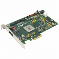
Manufacturer Part Number
DK-DEV-1AGX60N
Description
KIT DEV ARRIA GX 1AGX60N
Manufacturer
Altera
Series
Arria GXr
Type
FPGAr
Datasheet
1.EP1AGX20CF484C6N.pdf
(234 pages)
Specifications of DK-DEV-1AGX60N
Contents
Dev. Board, Quartus® II Web Edition, Reference Designs, Labs, and Complete Documentation
For Use With/related Products
1AGX60N
Lead Free Status / RoHS Status
Lead free / RoHS Compliant
Other names
544-2372
Available stocks
Company
Part Number
Manufacturer
Quantity
Price


2–90
Figure 2–76. Output Timing Diagram in DDR Mode
External RAM Interfacing
Table 2–23. DQS and DQ Bus Mode Support
Arria GX Device Handbook, Volume 1
EP1AGX20
EP1AGX35
EP1AGX50/60
EP1AGX90
Note to
(1) Numbers are preliminary until devices are available.
Device
Table
2–23:
484-pin FineLine BGA
484-pin FineLine BGA
780-pin FineLine BGA
484-pin FineLine BGA
780-pin FineLine BGA
1,152-pin FineLine
BGA
1,152-pin FineLine
BGA
From Internal
Registers
The Arria GX IOE operates in bidirectional DDR mode by combining the DDR input
and DDR output configurations. The negative-edge-clocked OE register holds the OE
signal inactive until the falling edge of the clock to meet DDR SDRAM timing
requirements.
In addition to the six I/O registers in each IOE, Arria GX devices also have dedicated
phase-shift circuitry for interfacing with external memory interfaces, including DDR,
DDR2 SDRAM, and SDR SDRAM. In every Arria GX device, the I/O banks at the top
(Banks 3 and 4) and bottom (Banks 7 and 8) of the device support DQ and DQS signals
with DQ bus modes of ×4, ×8/×9, ×16/×18, or ×32/×36.
of DQ and DQS buses that are supported per device.
A compensated delay element on each DQS pin automatically aligns input DQS
synchronization signals with the data window of their corresponding DQ data
signals. The DQS signals drive a local DQS bus in the top and bottom I/O banks. This
DQS bus is an additional resource to the I/O clocks and is used to clock DQ input
registers with the DQS signal.
DDR output
Package
CLK
A1
B1
B1
(Note 1)
Number of
×4 Groups
A1
18
18
36
36
2
2
2
B2
A2
B2
A2
A3
B3
B3
×8/×9 Groups
Number of
A3
18
18
A4
B4
0
0
8
0
8
B4
A4
×16/×18 Groups
Number of
Table 2–23
© December 2009 Altera Corporation
0
0
4
0
4
8
8
Chapter 2: Arria GX Architecture
shows the number
×32/×36 Groups
Number of
0
0
0
0
0
4
4
I/O Structure
Related parts for DK-DEV-1AGX60N
Image
Part Number
Description
Manufacturer
Datasheet
Request
R

Part Number:
Description:
KIT DEV ARRIA II GX FPGA 2AGX125
Manufacturer:
Altera
Datasheet:

Part Number:
Description:
KIT DEV CYCLONE III LS EP3CLS200
Manufacturer:
Altera
Datasheet:

Part Number:
Description:
KIT DEV STRATIX IV FPGA 4SE530
Manufacturer:
Altera
Datasheet:

Part Number:
Description:
KIT DEV FPGA 2AGX260 W/6.375G TX
Manufacturer:
Altera
Datasheet:

Part Number:
Description:
KIT DEV MAX V 5M570Z
Manufacturer:
Altera
Datasheet:

Part Number:
Description:
KIT DEV STRATIX V FPGA 5SGXEA7
Manufacturer:
Altera
Datasheet:

Part Number:
Description:
KIT DEVELOPMENT STRATIX III
Manufacturer:
Altera
Datasheet:

Part Number:
Description:
KIT DEVELOPMENT STRATIX IV
Manufacturer:
Altera
Datasheet:
Part Number:
Description:
KIT STARTER CYCLONE IV GX
Manufacturer:
Altera
Datasheet:
Part Number:
Description:
KIT DEVELOPMENT STRATIX IV
Manufacturer:
Altera
Datasheet:

Part Number:
Description:
CPLD, EP610 Family, ECMOS Process, 300 Gates, 16 Macro Cells, 16 Reg., 16 User I/Os, 5V Supply, 35 Speed Grade, 24DIP
Manufacturer:
Altera Corporation
Datasheet:
Part Number:
Description:
CPLD, EP610 Family, ECMOS Process, 300 Gates, 16 Macro Cells, 16 Reg., 16 User I/Os, 5V Supply, 15 Speed Grade, 24DIP
Manufacturer:
Altera Corporation
Datasheet: