DK-DEV-1AGX60N Altera, DK-DEV-1AGX60N Datasheet - Page 223
DK-DEV-1AGX60N
Manufacturer Part Number
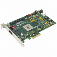
DK-DEV-1AGX60N
Description
KIT DEV ARRIA GX 1AGX60N
Manufacturer
Altera
Series
Arria GXr
Type
FPGAr
Datasheet
1.EP1AGX20CF484C6N.pdf
(234 pages)
Specifications of DK-DEV-1AGX60N
Contents
Dev. Board, Quartus® II Web Edition, Reference Designs, Labs, and Complete Documentation
For Use With/related Products
1AGX60N
Lead Free Status / RoHS Status
Lead free / RoHS Compliant
Other names
544-2372
Available stocks
Company
Part Number
Manufacturer
Quantity
Price


Chapter 4: DC and Switching Characteristics
High-Speed I/O Specifications
Table 4–114. High-Speed Timing Specifications and Definitions (Part 2 of 2)
Table 4–115. High-Speed I/O Specifications (Part 1 of
© December 2009 Altera Corporation
Timing unit interval (TUI)
f
f
Channel-to-channel skew (TCCS)
Sampling window (SW)
Input jitter
Output jitter
t
t
f
f
f
f
TCCS
SW
Output jitter
Output t
Output t
t
DPA run length
DPA jitter tolerance
High-Speed Timing Specifications
H S D R
H S D R D PA
D U T Y
L O CK
H S C L K
H S C L K
H S D R
H S D R D PA
D U T Y
(data rate)
(clock frequency)
= f
R I SE
F AL L
Symbol
(DPA data rate)
H S D R
/ W
Table 4–115
W = 2 to 32 (LVDS, HyperTransport technology)
W = 1 (SERDES bypass, LVDS only)
W = 1 (SERDES used, LVDS only)
J = 4 to 10 (LVDS, HyperTransport technology)
J = 2 (LVDS, HyperTransport technology)
J = 1 (LVDS only)
J = 4 to 10 (LVDS, HyperTransport technology)
All differential I/O standards
All differential I/O standards
All differential I/O standards
All differential I/O standards
Data channel peak-to-peak jitter
—
shows the high-speed I/O timing specifications.
The timing budget allowed for skew, propagation delays, and data sampling window.
(TUI = 1/(Receiver Input Clock Frequency × Multiplication Factor) = t
Maximum/minimum LVDS data transfer rate (f
Maximum/minimum LVDS data transfer rate (f
The timing difference between the fastest and slowest output edges, including t
variation and clock skew. The clock is included in the TCCS measurement.
The period of time during which the data must be valid in order to capture it
correctly. The setup and hold times determine the ideal strobe position within the
sampling window.
Peak-to-peak input jitter on high-speed PLLs.
Peak-to-peak output jitter on high-speed PLLs.
Duty cycle on high-speed transmitter output clock.
Lock time for high-speed transmitter and receiver PLLs.
Conditions
—
—
2)Note (1), (2)
Definitions
(3)
0.44
Min
150
150
150
440
16
16
(4)
(4)
—
—
—
—
45
—
H S D R
H S D R D P A
–6 Speed Grade
= 1/TUI), non-DPA.
= 1/TUI), DPA.
Typ
Arria GX Device Handbook, Volume 1
—
—
—
—
—
—
—
—
—
—
—
—
50
—
—
6,400
Max
420
500
640
840
700
500
840
200
190
290
290
—
55
—
C
/w).
Mbps
Mbps
Mbps
Mbps
Units
MHz
MHz
MHz
ps
ps
ps
ps
ps
UI
UI
%
C O
4–101
Related parts for DK-DEV-1AGX60N
Image
Part Number
Description
Manufacturer
Datasheet
Request
R

Part Number:
Description:
KIT DEV ARRIA II GX FPGA 2AGX125
Manufacturer:
Altera
Datasheet:

Part Number:
Description:
KIT DEV CYCLONE III LS EP3CLS200
Manufacturer:
Altera
Datasheet:

Part Number:
Description:
KIT DEV STRATIX IV FPGA 4SE530
Manufacturer:
Altera
Datasheet:

Part Number:
Description:
KIT DEV FPGA 2AGX260 W/6.375G TX
Manufacturer:
Altera
Datasheet:

Part Number:
Description:
KIT DEV MAX V 5M570Z
Manufacturer:
Altera
Datasheet:

Part Number:
Description:
KIT DEV STRATIX V FPGA 5SGXEA7
Manufacturer:
Altera
Datasheet:

Part Number:
Description:
KIT DEVELOPMENT STRATIX III
Manufacturer:
Altera
Datasheet:

Part Number:
Description:
KIT DEVELOPMENT STRATIX IV
Manufacturer:
Altera
Datasheet:
Part Number:
Description:
KIT STARTER CYCLONE IV GX
Manufacturer:
Altera
Datasheet:
Part Number:
Description:
KIT DEVELOPMENT STRATIX IV
Manufacturer:
Altera
Datasheet:

Part Number:
Description:
CPLD, EP610 Family, ECMOS Process, 300 Gates, 16 Macro Cells, 16 Reg., 16 User I/Os, 5V Supply, 35 Speed Grade, 24DIP
Manufacturer:
Altera Corporation
Datasheet:
Part Number:
Description:
CPLD, EP610 Family, ECMOS Process, 300 Gates, 16 Macro Cells, 16 Reg., 16 User I/Os, 5V Supply, 15 Speed Grade, 24DIP
Manufacturer:
Altera Corporation
Datasheet: