DK-DEV-1AGX60N Altera, DK-DEV-1AGX60N Datasheet - Page 104
DK-DEV-1AGX60N
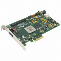
Manufacturer Part Number
DK-DEV-1AGX60N
Description
KIT DEV ARRIA GX 1AGX60N
Manufacturer
Altera
Series
Arria GXr
Type
FPGAr
Datasheet
1.EP1AGX20CF484C6N.pdf
(234 pages)
Specifications of DK-DEV-1AGX60N
Contents
Dev. Board, Quartus® II Web Edition, Reference Designs, Labs, and Complete Documentation
For Use With/related Products
1AGX60N
Lead Free Status / RoHS Status
Lead free / RoHS Compliant
Other names
544-2372
Available stocks
Company
Part Number
Manufacturer
Quantity
Price


2–98
Table 2–28. Board Design Recommendations for nCEO and nCE Input Buffer Power
Arria GX Device Handbook, Volume 1
nCE Input Buffer Power
VCCSEL
(V
VCCSEL
(V
VCCSEL
powered by
V
Notes to
(1) Input buffer is 3.3-V tolerant.
(2) The nCEO output buffer meets V
(3) Input buffer is 2.5-V tolerant.
(4) The nCEO output buffer meets V
(5) Input buffer is 1.8-V tolerant.
(6) An external 250- pull-up resistor is not required, but recommended if signal levels on the board are not optimal.
C C P D
CC I O
CC I O
in I/O Bank 3
= 3.3 V)
Bank 3 = 1.5 V)
Bank 3 = 1.8 V)
Table
high
high
low (nCE
2–28:
The TDO and nCEO pins are powered by V
I/O bank 4 and nCEO is in I/O Bank 7. Ideally, the V
any two connected pins are at the same voltage level. This may not always be possible
depending on the V
configuration voltage level chosen by V
devices can be in any position in the chain. The master device indicates that it is
driving out TDO or nCEO to a slave device. For multi-device passive configuration
schemes, the nCEO pin of the master device drives the nCE pin of the slave device. The
VCCSEL pin on the slave device selects which input buffer is used for nCE. When
V
logic low, it selects the 3.3-V/2.5-V input buffer powered by V
have the V
nCE input buffer of the slave device it is connected to, but that may not be possible
depending on the application.
Table 2–28
successfully drive nCE for all power supply combinations.
For JTAG chains, the TDO pin of the first device drives the TDI pin of the second
device in the chain. The V
TRST) is internally hardwired to GND selecting the 3.3-V/2.5-V input buffer powered
by V
match the V
depending on the application.
ensure proper JTAG chain operation.
CCSEL
V
CCPD
v
C C I O
v
is logic high, it selects the 1.8-V/1.5-V buffer powered by V
O H
O H
(1),
. The ideal case is to have the V
(1),
v
= 3.3 V
(MIN) = 2.4 V.
(MIN) = 2.0 V.
CC IO
contains board design recommendations to ensure that nCEO can
CCSEL
(2)
(2)
of the nCEO bank in a master device match the V
settings for TDI on the second device, but that may not be possible
CCIO
V
v
v
C C I O
Arria GX nCEO V
v
level of TDO and nCEO pins on master devices and the
(3),
(3),
CCSEL
= 2.5 V
(4)
(4)
(4)
Table 2–29
input on JTAG input I/O cells (TCK, TMS, TDI, and
CCIO
V
C C I O
CCSEL
CCIO
v
v
Voltage Level in I/O Bank 7
contains board design recommendations to
CCIO
v
= 1.8 V
of the TDO bank from the first device to
(5)
(6)
on slave devices. Master and slave
of the bank that they reside. TDO is in
CC
Level shifter
required
V
supplies for the I/O buffers of
C C I O
© December 2009 Altera Corporation
v
v
= 1.5 V
Chapter 2: Arria GX Architecture
CCPD
CCSEL
CCIO
. The ideal case is to
settings for the
. When V
Level shifter
required
Level shifter
required
V
C C I O
v
I/O Structure
= 1.2 V
CCSEL
is
Related parts for DK-DEV-1AGX60N
Image
Part Number
Description
Manufacturer
Datasheet
Request
R

Part Number:
Description:
KIT DEV ARRIA II GX FPGA 2AGX125
Manufacturer:
Altera
Datasheet:

Part Number:
Description:
KIT DEV CYCLONE III LS EP3CLS200
Manufacturer:
Altera
Datasheet:

Part Number:
Description:
KIT DEV STRATIX IV FPGA 4SE530
Manufacturer:
Altera
Datasheet:

Part Number:
Description:
KIT DEV FPGA 2AGX260 W/6.375G TX
Manufacturer:
Altera
Datasheet:

Part Number:
Description:
KIT DEV MAX V 5M570Z
Manufacturer:
Altera
Datasheet:

Part Number:
Description:
KIT DEV STRATIX V FPGA 5SGXEA7
Manufacturer:
Altera
Datasheet:

Part Number:
Description:
KIT DEVELOPMENT STRATIX III
Manufacturer:
Altera
Datasheet:

Part Number:
Description:
KIT DEVELOPMENT STRATIX IV
Manufacturer:
Altera
Datasheet:
Part Number:
Description:
KIT STARTER CYCLONE IV GX
Manufacturer:
Altera
Datasheet:
Part Number:
Description:
KIT DEVELOPMENT STRATIX IV
Manufacturer:
Altera
Datasheet:

Part Number:
Description:
CPLD, EP610 Family, ECMOS Process, 300 Gates, 16 Macro Cells, 16 Reg., 16 User I/Os, 5V Supply, 35 Speed Grade, 24DIP
Manufacturer:
Altera Corporation
Datasheet:
Part Number:
Description:
CPLD, EP610 Family, ECMOS Process, 300 Gates, 16 Macro Cells, 16 Reg., 16 User I/Os, 5V Supply, 15 Speed Grade, 24DIP
Manufacturer:
Altera Corporation
Datasheet: