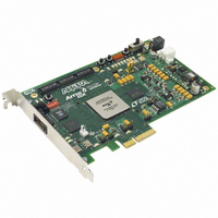
DK-DEV-1AGX60N Altera, DK-DEV-1AGX60N Datasheet - Page 44

DK-DEV-1AGX60N
Manufacturer Part Number
DK-DEV-1AGX60N
Description
KIT DEV ARRIA GX 1AGX60N
Manufacturer
Altera
Series
Arria GXr
Type
FPGAr
Datasheet
1.EP1AGX20CF484C6N.pdf
(234 pages)
Specifications of DK-DEV-1AGX60N
Contents
Dev. Board, Quartus® II Web Edition, Reference Designs, Labs, and Complete Documentation
For Use With/related Products
1AGX60N
Lead Free Status / RoHS Status
Lead free / RoHS Compliant
Other names
544-2372
Available stocks
Company
Part Number
Manufacturer
Quantity
Price
- Current page: 44 of 234
- Download datasheet (4Mb)
2–38
Arithmetic Mode
Figure 2–34. ALM in Arithmetic Mode
Arria GX Device Handbook, Volume 1
Arithmetic mode is ideal for implementing adders, counters, accumulators, wide
parity functions, and comparators. An ALM in arithmetic mode uses two sets of 2
four-input LUTs along with two dedicated full adders. The dedicated adders allow
the LUTs to be available to perform pre-adder logic; therefore, each adder can add the
output of two four-input functions. The four LUTs share the dataa and datab
inputs. As shown in
carry-out from adder0 feeds to carry-in of adder1. The carry-out from adder1
drives to adder0 of the next ALM in the LAB. ALMs in arithmetic mode can drive
out registered and/or unregistered versions of the adder outputs.
While operating in arithmetic mode, the ALM can support simultaneous use of the
adder’s carry output along with combinational logic outputs. In this operation, adder
output is ignored. This usage of the adder with the combinational logic output
provides resource savings of up to 50% for functions that can use this ability. An
example of such functionality is a conditional operation, such as the one shown in
Figure
Equation 2–1.
To implement this function, the adder is used to subtract ‘Y’ from ‘X.’ If ‘X’ is less than
‘Y,’ the carry_out signal is ‘1.’ The carry_out signal is fed to an adder where it
drives out to the LAB local interconnect. It then feeds to the LAB-wide syncload
signal. When asserted, syncload selects the syncdata input. In this case, the data
‘Y’ drives the syncdata inputs to the registers. If ‘X’ is greater than or equal to ‘Y,’ the
syncload signal is deasserted and ‘X’ drives the data port of the registers.
datae0
datae1
dataf0
dataf1
datab
dataa
datad
datac
2–35. The equation for this example is:
4-Input
4-Input
4-Input
4-Input
LUT
LUT
LUT
LUT
Figure
2–34, the carry-in signal feeds to adder0, and the
carry_out
carry_in
R = (X < Y) ? Y : X
adder0
adder1
D
D
reg0
reg1
Q
Q
To general or
To general or
To general or
local routing
To general or
local routing
local routing
local routing
© December 2009 Altera Corporation
Chapter 2: Arria GX Architecture
Adaptive Logic Modules
Related parts for DK-DEV-1AGX60N
Image
Part Number
Description
Manufacturer
Datasheet
Request
R

Part Number:
Description:
KIT DEV ARRIA II GX FPGA 2AGX125
Manufacturer:
Altera
Datasheet:

Part Number:
Description:
KIT DEV CYCLONE III LS EP3CLS200
Manufacturer:
Altera
Datasheet:

Part Number:
Description:
KIT DEV STRATIX IV FPGA 4SE530
Manufacturer:
Altera
Datasheet:

Part Number:
Description:
KIT DEV FPGA 2AGX260 W/6.375G TX
Manufacturer:
Altera
Datasheet:

Part Number:
Description:
KIT DEV MAX V 5M570Z
Manufacturer:
Altera
Datasheet:

Part Number:
Description:
KIT DEV STRATIX V FPGA 5SGXEA7
Manufacturer:
Altera
Datasheet:

Part Number:
Description:
KIT DEVELOPMENT STRATIX III
Manufacturer:
Altera
Datasheet:

Part Number:
Description:
KIT DEVELOPMENT STRATIX IV
Manufacturer:
Altera
Datasheet:

Part Number:
Description:
KIT STARTER CYCLONE IV GX
Manufacturer:
Altera
Datasheet:

Part Number:
Description:
KIT DEVELOPMENT STRATIX IV
Manufacturer:
Altera
Datasheet:

Part Number:
Description:
CPLD, EP610 Family, ECMOS Process, 300 Gates, 16 Macro Cells, 16 Reg., 16 User I/Os, 5V Supply, 35 Speed Grade, 24DIP
Manufacturer:
Altera Corporation
Datasheet:

Part Number:
Description:
CPLD, EP610 Family, ECMOS Process, 300 Gates, 16 Macro Cells, 16 Reg., 16 User I/Os, 5V Supply, 15 Speed Grade, 24DIP
Manufacturer:
Altera Corporation
Datasheet:


