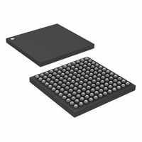
DS3141+ Maxim Integrated Products, DS3141+ Datasheet - Page 68

DS3141+
Manufacturer Part Number
DS3141+
Description
IC FRAMER DS3/E3 SNGL 144CSBGA
Manufacturer
Maxim Integrated Products
Datasheet
1.DS3141.pdf
(88 pages)
Specifications of DS3141+
Controller Type
DS3/E3 Framer
Interface
LIU
Voltage - Supply
3.135 V ~ 3.465 V
Current - Supply
80mA
Operating Temperature
-40°C ~ 85°C
Mounting Type
Surface Mount
Package / Case
144-CSBGA
Lead Free Status / RoHS Status
Lead free / RoHS Compliant
DS3141/DS3142/DS3143/DS3144 Single/Dual/Triple/Quad DS3/E3 Framers
8.4 Loopback Modes
The loopback modes are selected by setting the LLB, DLB, and/or PLB bits in the
MC2
register. See
Figure 1-1
for
a visual description of these loopbacks. At reset, none of the loopback modes are activated. PLB and DLB may not
be active at the same time. If LLB and PLB are both active at the same time, then TPOS/TNRZ, TNEG, and TCLK
are sourced from RPOS/RNRZ, RNEG/RLCV, and RCLK while the internal workings of the framer are in PLB
mode.
The line loopback (LLB) mode is used to send the received signal back toward the network. TAIS and TUA1 are
not available during line loopback, but the TPOS/TRNZ and TNEG pins can be forced high and low using the
TPOSH, TPOSI, TNEGH, and TNEGI bits in the
MC5
register.
The diagnostic loopback (DLB) mode is used to send the transmitted signal back toward the system through the
receive framer. When the framer is in diagnostic loopback, it can simultaneously transmit AIS to the far end if the
TAIS bit is set in the
T3E3CR1
register. The framer supports simultaneous line loopback and diagnostic loopback.
The payload loopback (PLB) mode is used to send the received payload back toward the network with new
overhead inserted. When the framer is in payload loopback, the internal transmit clock is connected to the internal
receive clock, internal transmit data is sourced from internal receive data, and TICLK and TDAT are ignored. The
TDEN and TSOF signals are aligned with the RDEN and RSOF signals, and TOH and TOHEN are still enabled.
The TSOF, TDEN, TOH, and TOHEN signals are timed relative to ROCLK rather than TICLK.
8.5 Transmit Overhead Insertion
The transmit signal can be overwritten at any bit location using the TOH and TOHEN signals. The TSOF signal
marks the start of the transmit frame and is used to determine which bits to overwrite. To overwrite a specific bit in
the DS3 or E3 frame, count the required number of TICLK cycles after the TSOF frame pulse. When the proper
TICLK cycle is reached, assert the TOHEN pin to replace normal transmit data (overhead or payload) with the
value on the TOH pin. One application for the TOH and TOHEN pins is to use some of the unused C bits in DS3
C-Bit Parity mode for a proprietary communications channel.
During payload loopback, the transmit side is timed from ROCLK rather than TICLK. If the system needs to support
transmit overhead insertion (TOH) during payload loopback (PLB), then TOH and TOHEN must also be timed with
respect to ROCLK. One way to access ROCLK is to set the TCCLK bit in the
MC2
register to convert the
TDEN/TGCLK output pin into a constant clock, which is based on ROCLK during payload loopback. TOH and
TOHEN can then be timed with respect to the constant clock on the TDEN/TGCLK pin.
68 of 88


