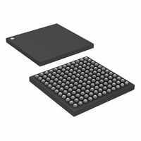
DS3141+ Maxim Integrated Products, DS3141+ Datasheet - Page 17

DS3141+
Manufacturer Part Number
DS3141+
Description
IC FRAMER DS3/E3 SNGL 144CSBGA
Manufacturer
Maxim Integrated Products
Datasheet
1.DS3141.pdf
(88 pages)
Specifications of DS3141+
Controller Type
DS3/E3 Framer
Interface
LIU
Voltage - Supply
3.135 V ~ 3.465 V
Current - Supply
80mA
Operating Temperature
-40°C ~ 85°C
Mounting Type
Surface Mount
Package / Case
144-CSBGA
Lead Free Status / RoHS Status
Lead free / RoHS Compliant
6.1 Status Register Description
There are two types of bits used to build the status and information registers. The real-time status register bit
indicates the state of the corresponding signal at the time it was read. The latched status register bit is set when
the corresponding signal changes state (low-to-high, high-to-low, or both, depending on the bit). The latched status
bit is cleared when written with logic 1 and is not set again until the corresponding signal changes state again.
The following is example host-processor pseudocode that checks to see if the BERT SYNC status has changed:
If ((BSRL and 01h) neq 0) then
There are four suffixes used for status and information register names: SR for real-time status registers, SRL for
latched status registers, SRIE for interrupt-enable registers, and IR for information registers. Latched status bits
have the suffix “L” and interrupt-enable bits have the suffix “IE.” The bits in the SR, SRL, and SRIE registers are
arranged such that related real-time status, latched status, and interrupt-enable bits are located in the same bit
position in neighboring registers. For example,
status bit SYNCL, and the interrupt-enable bit SYNCIE are all located in bit 0 of their respective registers (BSR,
BSRL, and BSRIE).
When set, most latched status register bits can cause an interrupt on the INT pin if the corresponding interrupt-
enable register bit is also set. Most latched status register bits have an associated real-time status register bit.
Information registers can contain a mix of real-time and latched status bits, none of which can cause an interrupt.
Table 6-B. Status Register Set Example
Figure 6-1. Status Register Interrupt Flow
REGISTER
BSRIE
BSRL
BSR
BSRL = 01h
If ((BSR and 01h) neq 0) then
Else
EVENT
WR
WR
–––––
–––––
BIT 7
N/A
N/A
N/A
BIT 6
LATCHED STATUS REGISTER
N/A
N/A
N/A
INT ENABLE
CLEAR ON WRITE LOGIC 1
REGISTER
SET ON EVENT DETECT
BIT 5
RA1L
RA1
N/A
Table 6-B
// SYNCL bit is set
RA0L
BIT 4
RA0
N/A
17 of 88
// Clear SYNCL bit only
// BERT has changed to in sync
// BERT has changed to out of sync
shows that the real-time status bit SYNC, the latched
OTHER INT
SOURCE
BEDIE
BEDL
BIT 3
N/A
REAL-TIME STATUS
LATCHED STATUS
BBCOIE
BBCOL
BBCO
BIT 2
BECOIE
BECOL
BECO
BIT 1
SYNCIE
SYNCL
SYNC
BIT 0
SR
SRL
INT


