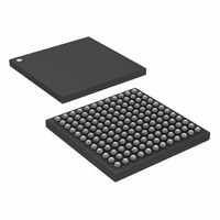
DS3141+ Maxim Integrated Products, DS3141+ Datasheet - Page 54

DS3141+
Manufacturer Part Number
DS3141+
Description
IC FRAMER DS3/E3 SNGL 144CSBGA
Manufacturer
Maxim Integrated Products
Datasheet
1.DS3141.pdf
(88 pages)
Specifications of DS3141+
Controller Type
DS3/E3 Framer
Interface
LIU
Voltage - Supply
3.135 V ~ 3.465 V
Current - Supply
80mA
Operating Temperature
-40°C ~ 85°C
Mounting Type
Surface Mount
Package / Case
144-CSBGA
Lead Free Status / RoHS Status
Lead free / RoHS Compliant
HDLC controller stops accepting packets until either the FIFO is completely emptied or reset. If the receive HDLC
detects an incoming abort (seven or more 1s in a row), it sets the receive abort sequence-detected (RABTL) status
bit. If an abort sequence is detected in the middle of an incoming packet, then the receive HDLC controller sets the
packet status bits accordingly in the receive FIFO.
The receive HDLC controller has been designed to minimize its real-time host processor support requirements. The
256-byte receive FIFO is deep enough to store the three DS3 packets (path ID, idle signal ID, and test signal ID)
that arrive once a second. Thus, in DS3 applications the host processor only needs to read the receive HDLC FIFO
once a second to retrieve the three messages. The host processor can be notified when the beginning of a new
packet is received (receive packet-start status bit) and when the end of a packet is received (receive packet-end
status bit). Also, the host processor can be notified when the FIFO has filled beyond a programmable level called
the high watermark. The host processor reads the incoming packet data out of the receive FIFO one byte at a time.
When the receive FIFO is empty, the REMPTY bit in the HDLC information register (HIR) is set.
7.10.2 Transmit Operation
On reset, the transmit HDLC controller flushes the transmit FIFO and transmits an abort followed by either 7Eh or
FFh (depending on the setting of the TFS control bit) continuously. The transmit HDLC controller then waits until
there are at least two bytes in the transmit FIFO before starting to send the packet. The transmit HDLC
automatically adds an opening flag of 7Eh to the beginning of the packet and zero stuffs the outgoing data stream.
When the transmit HDLC controller detects that the TMEND bit in the transmit FIFO is set, it automatically
calculates and appends the 16-bit CRC checksum followed by a closing flag of 7Eh. If the FIFO is empty, the
transmit HDLC controller sends either 7Eh or FFh continuously. When new data arrives in the FIFO, the transmit
HDLC automatically transmits the opening flag and begins sending the next packet. Between consecutive packets,
there are always at least two flags. If the transmit FIFO ever empties when a packet is being sent (i.e., before the
TMEND bit is set), then the transmit HDLC controller sets the transmit FIFO underrun (TUDRL) status bit and
sends an abort of seven 1s in a row (FEh) followed by continuous transmission of either 7Eh (flags) or FFh (idle).
When the FIFO underruns, the transmit HDLC controller should be reset by the host processor.
The transmit HDLC controller has been designed to minimize its real-time host processor support requirements.
The 256-byte transmit FIFO is deep enough to store the three DS3 packets (path ID, idle signal ID, and test signal
ID) that should be sent once a second. Thus, in DS3 applications the host processor only needs to write the
transmit HDLC FIFO once a second to send the three messages. Once the host processor has written an outgoing
packet, it can monitor the transmit packet-end (TENDL) status bit to know when the packet has been sent. Also,
the host processor can be notified when the FIFO has emptied below a programmable level called the low
watermark. The host processor must never overfill the FIFO. To keep this from occurring, the host processor can
obtain the real-time depth of the transmit FIFO through the transmit FIFO level bits in the HDLC information register
(HIR).
7.10.3 HDLC Register Description
Table 7-H. HDLC Register Map
ADDR
5Ch
5Dh
5Eh
5Fh
50h
51h
54h
55h
56h
57h
REGISTER
RHDLC1
RHDLC2
THDLC1
THDLC2
HSRIE
HCR1
HCR2
HSRL
HSR
HIR
ROVRIE
ROVRL
BIT 7
RHR
N/A
N/A
N/A
N/A
N/A
D7
D7
RHWMS2
RPEIE
RPEL
BIT 6
THR
N/A
N/A
N/A
N/A
D6
D6
RHWMS1
REMPTY
RPSIE
RPSL
BIT 5
RID
N/A
N/A
N/A
D5
D5
54 of 88
RHWMS0
TEMPTY
RABTIE
RABTL
BIT 4
TID
N/A
N/A
N/A
D4
D4
RHWMIE
RHWML
RHWM
BIT 3
TFL3
TFS
PS1
N/A
N/A
D3
D3
TLWMS2
TLWMIE
TLWML
TLWM
TZSD
BIT 2
TFL2
PS0
N/A
D2
D2
TLWMS1
TUDRIE
TUDRL
CBYTE
TCRCI
BIT 1
TFL1
N/A
N/A
D1
D1
TLWMS0
TENDIE
TCRCD
TMEND
TENDL
OBYTE
BIT 0
TFL0
N/A
D0
D0


