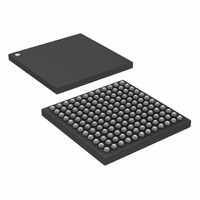
DS3141+ Maxim Integrated Products, DS3141+ Datasheet - Page 43

DS3141+
Manufacturer Part Number
DS3141+
Description
IC FRAMER DS3/E3 SNGL 144CSBGA
Manufacturer
Maxim Integrated Products
Datasheet
1.DS3141.pdf
(88 pages)
Specifications of DS3141+
Controller Type
DS3/E3 Framer
Interface
LIU
Voltage - Supply
3.135 V ~ 3.465 V
Current - Supply
80mA
Operating Temperature
-40°C ~ 85°C
Mounting Type
Surface Mount
Package / Case
144-CSBGA
Lead Free Status / RoHS Status
Lead free / RoHS Compliant
Register Name:
Register Description:
Register Address:
Bit #
Name
Default
Register Name:
Register Description:
Register Address:
Bit #
Name
Default
Bits 0 to 15: Frame Error Count (FE[15:0]). This count register contains the value of the internal framer error
counter latched during the last error counter update. The internal counter counts either the number of OOF
occurrences or the number of framing bit errors received. The type of counting is configured through the FECC[1:0]
control bits in the
When the counter is configured to count OOF occurrences, it increments by one each time the framer loses receive
synchronization. When the counter is configured to count framing bit errors, the counter can be configured through
the ECC control bit in the
not.
Register Name:
Register Description:
Register Address:
Bit #
Name
Default
Register Name:
Register Description:
Register Address:
Bit #
Name
Default
Bits 0 to 15: P-Bit Parity Error Count (PE[15:0]). This count register contains the value of the internal P-bit parity
error counter latched during the last error counter update. The internal counter counts the number of DS3 P-bit
parity errors. In E3 mode this counter is meaningless and should be ignored. A P-bit parity error is defined as an
occurrence when the two P bits in a DS3 frame do not match one another or when the two P bits do not match the
parity calculation made on the information bits. Through the ECC control bit in the
can be configured to either continue counting P-bit parity errors during an OOF event or not.
FECC[1:0]
00
01
10
11
DS3 Mode: Count OOF occurrences
E3 Mode: Count OOF occurrences
DS3 Mode: Count both F-bit and M-bit errors
E3 Mode: Count bit errors in the FAS word
DS3 Mode: Count only F-bit errors
E3 Mode: Count word errors in the FAS word
DS3 Mode: Count only M-bit errors
E3 Mode: Illegal state
PE15
FE15
PE7
FE7
7
0
7
0
7
0
7
0
T3E3CR2
Frame Error-Count Register (FECR1) Configuration
T3E3CR2
PE14
register. The possible configurations are shown below.
FE14
PE6
FE6
6
0
6
0
6
0
6
0
FECR1
Frame Error Count Register 1
24h
FECR2
Frame Error Count Register 2
25h
PCR1
P-Bit Parity Error Count Register 1
26h
PCR2
P-Bit Parity Error Count Register 2
27h
register to either continue counting frame bit errors during an OOF event or
PE13
FE13
PE5
FE5
5
0
5
0
5
0
5
0
43 of 88
PE12
FE12
PE4
FE4
4
0
4
0
0
0
4
4
PE11
PE3
FE11
FE3
3
0
3
0
3
0
3
0
PE10
PE2
FE10
FE2
2
0
2
0
2
0
2
0
T3E3CR2
PE1
PE9
FE1
FE9
1
0
1
0
register, the counter
1
0
1
0
PE0
PE8
FE0
FE8
0
0
0
0
0
0
0
0


