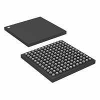
DS3141+ Maxim Integrated Products, DS3141+ Datasheet - Page 36

DS3141+
Manufacturer Part Number
DS3141+
Description
IC FRAMER DS3/E3 SNGL 144CSBGA
Manufacturer
Maxim Integrated Products
Datasheet
1.DS3141.pdf
(88 pages)
Specifications of DS3141+
Controller Type
DS3/E3 Framer
Interface
LIU
Voltage - Supply
3.135 V ~ 3.465 V
Current - Supply
80mA
Operating Temperature
-40°C ~ 85°C
Mounting Type
Surface Mount
Package / Case
144-CSBGA
Lead Free Status / RoHS Status
Lead free / RoHS Compliant
Bit 7: Manual Error-Insert Mode Select (MEIMS). When this bit is logic 0, the framer inserts errors on each 0-to-1
transition of the BPVI, EXZI, T3PBEI, T3CPBEI, or FBEI control bits. When this bit is logic 1, the framer inserts
errors on each 0-to-1 transition of the TMEI input signal. The appropriate BPVI, EXZI, T3PBEI, T3CPBEI, or FBEI
control bit must be set to 1 for this to occur. If all of the BPVI, EXZI, T3PBEI, T3CPBEI, and FBEI control bits are
set to 0, no errors are inserted.
Register Name:
Register Description:
Register Address:
Bit #
Name
Default
Bit 0: Loss-of-Signal Occurrence (LOS). This real-time status bit is set when the framer detects loss-of-signal
and cleared when the LOS condition terminates. The LOS alarm criteria are described in
Note: The LOS status bit is only valid when the framer is in dual-rail (POS/NEG) interface mode. When the framer is in binary (NRZ) interface
mode, LOS status must be sourced from the neighboring LIU. The reason for this is that in binary mode the neighboring LIU performs
B3ZS/HDB3 decoding—substituting zeros for B3ZS/HDB3 codewords—before passing the received traffic to the framer. Because this decoded
traffic can legitimately have long strings of zeros in it, the framer cannot look for and declare LOS in binary mode. In general, the IC that does
the B3ZS/HDB3 decoding must provide the LOS status information.
Bit 1: Out-of-Frame Occurrence (OOF). This real-time status bit is set when the framer detects an OOF condition
and cleared when the OOF condition terminates. The OOF defect criteria are described in
Bit 2: Alarm Indication Signal Detected (AIS). This real-time status bit is set when the framer detects an
incoming AIS and cleared when the AIS condition terminates. The AIS alarm criteria are described in
Table
Bit 3: Remote Alarm Indication Detected (RAI). This real-time status bit is set when the framer detects an
incoming RAI signal on the X bits or Sa bits and cleared when the RAI condition terminates. The RAI alarm criteria
are described in
operated in DS3 C-Bit Parity mode, but this bit does not indicate the FEAC alarm code detection.
Bit 4: DS3 Idle-Signal Detected (T3IDLE). This real-time status bit is set when the framer detects an incoming
DS3 idle signal and cleared when the idle signal terminates. The DS3 idle signal alarm criteria are described in
Table
Bit 5: Severely Errored-Frame Detected (SEF). This real-time status bit is set when the frame detects a severely
errored frame condition and cleared when the SEF condition clears. The SEF defect criteria are described in
Table
7-F.
7-Eand
7-Eand
0 = use 0-to-1 transition on the BPVI, EXZI, T3PBEI, T3CPBEI, or FBEI control bits to insert errors
1 = use 0-to-1 transition on the TMEI input signal to insert errors
Table
Table
N/A
—
7
Table
7-F. When the framer is operated in the E3 mode, this status bit should be ignored.
7-F.
7-Eand
N/A
—
6
Table
T3E3SR
DS3/E3 Status Register
18h
7-F. RAI can also be indicated through FEAC codes when the framer is
SEF
—
5
T3IDLE
36 of 88
—
4
RAI
—
3
AIS
—
2
Table
Table
OOF
—
1
7-Eand
7-Eand
Table
Table
Table
LOS
—
0
7-Eand
7-F.
7-F.


