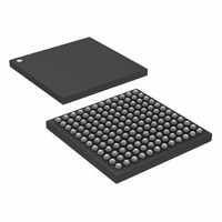
DS3141+ Maxim Integrated Products, DS3141+ Datasheet - Page 20

DS3141+
Manufacturer Part Number
DS3141+
Description
IC FRAMER DS3/E3 SNGL 144CSBGA
Manufacturer
Maxim Integrated Products
Datasheet
1.DS3141.pdf
(88 pages)
Specifications of DS3141+
Controller Type
DS3/E3 Framer
Interface
LIU
Voltage - Supply
3.135 V ~ 3.465 V
Current - Supply
80mA
Operating Temperature
-40°C ~ 85°C
Mounting Type
Surface Mount
Package / Case
144-CSBGA
Lead Free Status / RoHS Status
Lead free / RoHS Compliant
7.4 Error Insertion
Errors can be created in the transmit overhead and line coding for diagnostic purposes. These errors do not cause
any loss of data when created. The
The TMEI input pin can also be used to create errors.
7.5 Loopbacks
7.5.1 Line Loopback
The line loopback connects the incoming DS3/E3 data (RCLK, RPOS/RNRZ, and RNEG inputs) directly back to
the transmit side (TCLK, TPOS/TNRZ, and TNEG outputs). When this loopback is enabled, the incoming data
continues to pass through the receive framer block, but the output data from the transmit formatter is ignored. See
Figure 1-1
loopback.
7.5.2 Diagnostic Loopback
The diagnostic loopback sends the outgoing DS3/E3 data directly back to the receive side. When this loopback is
enabled, the incoming receive data at RCLK, RPOS, and RNEG is ignored. See
of this loopback. During diagnostic loopback the device can simultaneously generate AIS at the TCLK, TPOS, and
TNEG outputs, while regular traffic is looped back to the receiver. This feature keeps the diagnostic signal that is
being looped back from disturbing downstream equipment. Setting the DLB bit in the
diagnostic loopback.
7.5.3 Payload Loopback
The payload loopback sends the DS3/E3 payload from the receive framer back to the transmit formatter. When this
loopback is enabled, the incoming receive data continues to be present on the RDAT pin, but the transmit data on
the TDAT pin is ignored. During payload loopback, the TSOF and TDEN signals are realigned to the receive frame,
and the signals at TOH and TOHEN are active and can still overwrite any bit position. See
description of this loopback. During payload loopback TSOF, TDEN, TOHEN, and TOH are aligned to the ROCLK
signal. When PLB and DLB are both set, diagnostic loopback takes precedence. Setting the PLB bit in the
register activates payload loopback.
7.5.4 BERT and Loopback Interaction
Table 7-A
loopbacks active. The BERT mode is set in the BM[1:0] bits in the
BENA bit is set in the
various combinations of BERT modes and loopbacks active.
Table 7-A. BERT/Loopback Interaction—Payload Bits
DLB
0
0
1
1
0
0
0
0
0
CONFIGURATION BITS
LLB
0
0
0
0
1
1
0
0
0
describes how the payload bits move through the device with various combinations of BERT modes and
for a visual description of this loopback. Setting the LLB bit in the
PLB
0
0
0
0
0
0
1
1
1
BM [1:0]
BCR1
0X
1X
0X
1X
0X
1X
1X
00
01
register.
BERT and RDAT
Not used
Not used
TPOS/TNEG
RDAT and BERT
TPOS/TNEG
Not used
TPOS/TNEG, RDAT, and
BERT
TPOS/TNEG and RDAT
and BERT
From RPOS/RNEG To:
T3E3EIC
Table 7-B
error insertion register contains all the control bits to create errors.
describes how the overhead bits move through the device with
20 of 88
BITS AT PAYLOAD BIT POSITIONS
Not used
BERT and TPOS/TNEG
Not used
BERT and TPOS/TNEG
Not used
BERT
Not used
Not used
BERT
From TDAT To:
BCR1
register. The BERT is enabled when the
Figure 1-1
MC2
TPOS/TNEG
RDAT
TPOS/TNEG, BERT, and
RDAT
RDAT
Not used
RDAT
Not used
TPOS/TNEG
RDAT
MC2
register activates the line
for a visual description
Figure 1-1
From BERT To:
register activates the
for a visual
MC2


