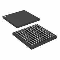
DS3141+ Maxim Integrated Products, DS3141+ Datasheet - Page 57

DS3141+
Manufacturer Part Number
DS3141+
Description
IC FRAMER DS3/E3 SNGL 144CSBGA
Manufacturer
Maxim Integrated Products
Datasheet
1.DS3141.pdf
(88 pages)
Specifications of DS3141+
Controller Type
DS3/E3 Framer
Interface
LIU
Voltage - Supply
3.135 V ~ 3.465 V
Current - Supply
80mA
Operating Temperature
-40°C ~ 85°C
Mounting Type
Surface Mount
Package / Case
144-CSBGA
Lead Free Status / RoHS Status
Lead free / RoHS Compliant
Register Name:
Register Description:
Register Address:
Bit #
Name
Default
Note: See
Bit 0: Transmit Packet-End Latched (TENDL). This latched status bit is set to 1 each time the transmit HDLC
controller reads a transmit FIFO byte with the corresponding TMEND bit set or when a FIFO underrun occurs.
TENDL is cleared when the host processor writes a 1 to it. When TENDL is set, it can cause a hardware interrupt
to occur if the TENDIE bit in the
interrupt is cleared when this bit is cleared or one or both of the interrupt-enable bits are cleared.
Bit 1: Transmit FIFO Underrun Latched (TUDRL). This latched status bit is set to 1 each time the transmit FIFO
underruns. TUDRL is cleared when the host processor writes a 1 to it and is not set again until another underrun
occurs (i.e., the FIFO has been written to and then allowed to empty again without the TMEND bit set). When
TUDRL is set, it can cause a hardware interrupt to occur if the TUDRIE bit in the
bit in the
interrupt-enable bits are cleared.
Bit 2: Transmit FIFO Low Watermark Latched (TLWML). This latched status bit is set to 1 when the TLWM
status bit in the
again until TLWM goes high again. When TLWML is set, it can cause a hardware interrupt to occur if the TLWMIE
bit in the
when this bit is cleared or one or both of the interrupt-enable bits are cleared.
Bit 3: Receive FIFO High Watermark Latched (RHWML). This latched status bit is set to 1 when the RHWM
status bit in the
set again until RHWM goes high again. When RHWML is set, it can cause a hardware interrupt to occur if the
RHWMIE bit in the
cleared when this bit is cleared or one or both of the interrupt-enable bits are cleared.
Bit 4: Receive Abort Sequence Detected Latched (RABTL). This latched status bit is set to 1 each time the
receive HDLC controller detects an abort sequence (seven or more 1s in a row) during packet reception. If the
receive HDLC is not currently receiving a packet, then receiving an abort sequence does not set this status bit.
RABTL is cleared when the host processor writes a 1 to it and is not set again until another abort is detected (at
least one valid flag must be detected before another abort can be detected). When RABTL is set, it can cause a
hardware interrupt to occur if the RABTIE bit in the
both set to 1. The interrupt is cleared when this bit is cleared or one or both of the interrupt-enable bits are cleared.
Bit 5: Receive Packet-Start Latched (RPSL). This latched status bit is set to 1 each time the receive HDLC
controller detects the start of an HDLC packet. RPSL is cleared when the host processor writes a 1 to it and is not
set again until another start of packet is detected. When RPSL is set, it can cause a hardware interrupt to occur if
the RPSIE bit in the
cleared when this bit is cleared or one or both of the interrupt-enable bits are cleared.
Bit 6: Receive Packet-End Latched (RPEL). This latched status bit is set to 1 each time the HDLC controller
detects a closing flag during reception of a packet, regardless of whether the packet is valid (CRC correct) or not
(bad CRC, abort sequence detected, packet too small, not an integral number of octets, or an overrun occurred).
RPEL is cleared when the host processor writes a 1 to it and is not set again until another message end is
detected. When RPEL is set, it can cause a hardware interrupt to occur if the RPEIE bit in the
the HDLCIE bit in the
both of the interrupt-enable bits are cleared.
Figure 7-7
MSRIE
HSRIE
ROVRL
HSR
HSR
—
7
for details on the interrupt signal flow for the status bits in the HSRL register.
register and the HDLCIE bit in the
register are both set to 1. The interrupt is cleared when this bit is cleared or one or both of the
HSRIE
HSRIE
register goes high. TLWML is cleared when the host processor writes a 1 to it and is not set
register goes high. RHWML is cleared when the host processor writes a one to it and is not
MSRIE
RPEL
register and the HDLCIE bit in the
—
register and the HDLCIE bit in the
6
register are both set to 1. The interrupt is cleared when this bit is cleared or one or
HSRIE
HSRL
HDLC Status Register Latched
55h
RPSL
—
5
register and the HDLCIE bit in the
RABTL
HSRIE
57 of 88
MSRIE
—
4
register and the HDLCIE bit in the
register are both set to one. The interrupt is cleared
MSRIE
MSRIE
RHWML
—
3
register are both set to 1. The interrupt is
register are both set to 1. The interrupt is
MSRIE
TLWML
—
2
HSRIE
register are both set to 1. The
register and the HDLCIE
TUDRL
—
1
HSRIE
MSRIE
register and
register are
TENDL
—
0


