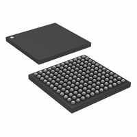
DS3141+ Maxim Integrated Products, DS3141+ Datasheet - Page 42

DS3141+
Manufacturer Part Number
DS3141+
Description
IC FRAMER DS3/E3 SNGL 144CSBGA
Manufacturer
Maxim Integrated Products
Datasheet
1.DS3141.pdf
(88 pages)
Specifications of DS3141+
Controller Type
DS3/E3 Framer
Interface
LIU
Voltage - Supply
3.135 V ~ 3.465 V
Current - Supply
80mA
Operating Temperature
-40°C ~ 85°C
Mounting Type
Surface Mount
Package / Case
144-CSBGA
Lead Free Status / RoHS Status
Lead free / RoHS Compliant
7.8 DS3/E3 Performance Error Counters
There are six internal error counters and six corresponding error count registers in the DS3/E3 framer. All the error
counters and count registers are 16 bits in length. The framer can be configured to update the count registers with
the latest counter values automatically once a second or manually through either the MECU bit in the
or the RECU input pin. When the count registers are updated through any of these methods, the internal error
counters are reset to 0. All the error counters saturate when full and do not roll over. When any of the error
counters are saturated, the COVF bit is set in the
Register Name:
Register Description:
Register Address:
Bit #
Name
Default
Register Name:
Register Description:
Register Address:
Bit #
Name
Default
Bits 0 to 15: Bipolar Violation Count (BPV[15:0]). This count register contains the value of the internal BPV/CV
error counter latched during the last error counter update. In DS3 mode, the internal counter counts bipolar
violations (BPV). In the E3 mode, the counter can be configured through the E3CVE bit in the
count BPVs or code violations (CVs). A BPV is defined as consecutive pulses (or marks) of the same polarity that
are not part of a B3ZS/HDB3 codeword. A CV is defined in ITU O.162 as two consecutive BPVs of the same
polarity. When the line interface is in binary mode (BIN = 1 in the
each RCLK clock cycle that the RLCV pin is active. The RLCV pin is normally active high but can be inverted using
the RNEGI bit in the
loopback (DLB = 1 in register MC2).
Register Name:
Register Description:
Register Address:
Bit #
Name
Default
Register Name:
Register Description:
Register Address:
Bit #
Name
Default
Bits 0 to 15: Excessive Zero Count (EXZ[15:0]). This count register contains the value of the internal EXZ error
counter latched during the last error counter update. The internal counter counts excessive zero occurrences
(EXZ). An EXZ occurrence is defined as three or more consecutive 0s in DS3 mode and four or more consecutive
0s in E3 mode. As an example, a string of eight consecutive 0s is a single EXZ occurrence and would only
increment this counter once.
BPV15
EXZ15
BPV7
EXZ7
7
0
7
0
7
0
7
0
MC5
BPV14
EXZ14
BPV6
EXZ6
register. The BPV counter ignores the RLCV pin when the device is in diagnostic
6
0
6
0
6
0
6
0
BPVCR1
Bipolar Violation Count Register 1
20h
BPVCR2
Bipolar Violation Count Register 2
21h
EXZCR1
Excessive Zero Count Register 1
22h
EXZCR2
Excessive Zero Count Register 2
23h
BPV13
EXZ13
BPV5
EXZ5
5
0
5
0
5
0
5
0
MSR
BPV12
EXZ12
42 of 88
BPV4
EXZ4
register.
0
0
0
0
4
4
4
4
MC1
BPV11
EXZ11
BPV3
EXZ3
3
0
3
0
3
0
3
0
register), the internal counter increments for
BPV10
EXZ10
BPV2
EXZ2
2
0
2
0
2
0
2
0
BPV1
BPV9
EXZ1
EXZ9
T3E3CR2
1
0
1
0
1
0
1
0
MC1
register to
BPV0
BPV8
EXZ0
EXZ8
register
0
0
0
0
0
0
0
0


