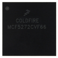
MCF5272CVF66 Freescale Semiconductor, MCF5272CVF66 Datasheet - Page 439

MCF5272CVF66
Manufacturer Part Number
MCF5272CVF66
Description
IC MPU 32BIT 66MHZ 196-MAPBGA
Manufacturer
Freescale Semiconductor
Series
MCF527xr
Specifications of MCF5272CVF66
Core Processor
Coldfire V2
Core Size
32-Bit
Speed
66MHz
Connectivity
EBI/EMI, Ethernet, I²C, SPI, UART/USART, USB
Peripherals
DMA, WDT
Number Of I /o
32
Program Memory Size
16KB (4K x 32)
Program Memory Type
ROM
Ram Size
1K x 32
Voltage - Supply (vcc/vdd)
3 V ~ 3.6 V
Oscillator Type
External
Operating Temperature
-40°C ~ 85°C
Package / Case
196-MAPBGA
Family Name
MCF5xxx
Device Core
ColdFire
Device Core Size
32b
Frequency (max)
66MHz
Instruction Set Architecture
RISC
Supply Voltage 1 (typ)
3.3V
Operating Temp Range
-40C to 85C
Operating Temperature Classification
Industrial
Mounting
Surface Mount
Pin Count
196
Package Type
MA-BGA
Lead Free Status / RoHS Status
Contains lead / RoHS non-compliant
Eeprom Size
-
Data Converters
-
Lead Free Status / Rohs Status
Not Compliant
Available stocks
Company
Part Number
Manufacturer
Quantity
Price
Company:
Part Number:
MCF5272CVF66
Manufacturer:
Freescale Semiconductor
Quantity:
10 000
Part Number:
MCF5272CVF66
Manufacturer:
FREESCALE
Quantity:
20 000
Company:
Part Number:
MCF5272CVF66 K75N
Manufacturer:
ST
Quantity:
18
Company:
Part Number:
MCF5272CVF66J
Manufacturer:
Freescale Semiconductor
Quantity:
10 000
- Current page: 439 of 544
- Download datasheet (7Mb)
19.13.10 Receive Error (E_RxER/PB14)
Ethernet mode: E_RxER is an input signal which when asserted along with E_RxDV signals that the PHY
has detected an error in the current frame. When E_RxDV is not asserted E_RxER has no effect. Applies
to MII mode operation.
Port B mode: This pin can also be configured as PB14 I/O.
19.13.11 Management Data Clock (E_MDC/PB15)
Ethernet mode: E_MDC is an output clock which provides a timing reference to the PHY for data transfers
on the E_MDIO signal. Applies to MII mode operation.
Port B mode: This pin can also be configured as I/O pin PB15.
19.13.12 Management Data (E_MDIO)
The bidirectional E_MDIO signal transfers control information between the external PHY and the
media-access controller. Data is synchronous to E_MDC. Applies to MII mode operation. This signal is
an input after reset. When the FEC is operated in 10Mbps 7-wire interface mode, this signal should be
connected to Vss.
19.13.13 Transmit Error (E_TxER)
Ethernet mode: When the E_TxER output is asserted for one or more clock cycles while E_TxEN is also
asserted, the PHY sends one or more illegal symbols. E_TxER has no effect at 10 Mbps or when E_TxEN
is negated. Applies to MII mode operation.
19.13.14 Carrier Receive Sense (E_CRS)
E_CRS is an input signal which when asserted signals that transmit or receive medium is not idle. Applies
to MII mode operation.
19.14 PWM Module Signals (PWM_OUT0–PWM_OUT2])
PWM_OUT0–PWM_OUT2 are the outputs of the compare logic within the pulse-width modulator
(PWM) modules.
19.15 Queued Serial Peripheral Interface (QSPI) Signals
This section describes signals used by the queued serial peripheral interface (QSPI) module. Four QSPI
chip selects, QSPI_CS[3:0], are multiplexed with the physical layer interface pins and GPIO port A.
QSPI_CS0 is always available. QSPI_CS3 is multiplexed with DOUT3 and PA7.
Freescale Semiconductor
•
•
•
PWM_OUT0 is always available.
PWM_OUT1 is multiplexed with TOUT1.
PWM_OUT2 is multiplexed with TIN1.
MCF5272 ColdFire
®
Integrated Microprocessor User’s Manual, Rev. 3
Signal Descriptions
19-29
Related parts for MCF5272CVF66
Image
Part Number
Description
Manufacturer
Datasheet
Request
R
Part Number:
Description:
Mcf5272 Coldfire Integrated Microprocessor User
Manufacturer:
Freescale Semiconductor, Inc
Datasheet:

Part Number:
Description:
MCF5272 Interrupt Service Routine for the Physical Layer Interface Controller
Manufacturer:
Freescale Semiconductor / Motorola
Datasheet:
Part Number:
Description:
Manufacturer:
Freescale Semiconductor, Inc
Datasheet:
Part Number:
Description:
Manufacturer:
Freescale Semiconductor, Inc
Datasheet:
Part Number:
Description:
Manufacturer:
Freescale Semiconductor, Inc
Datasheet:
Part Number:
Description:
Manufacturer:
Freescale Semiconductor, Inc
Datasheet:
Part Number:
Description:
Manufacturer:
Freescale Semiconductor, Inc
Datasheet:
Part Number:
Description:
Manufacturer:
Freescale Semiconductor, Inc
Datasheet:
Part Number:
Description:
Manufacturer:
Freescale Semiconductor, Inc
Datasheet:
Part Number:
Description:
Manufacturer:
Freescale Semiconductor, Inc
Datasheet:
Part Number:
Description:
Manufacturer:
Freescale Semiconductor, Inc
Datasheet:
Part Number:
Description:
Manufacturer:
Freescale Semiconductor, Inc
Datasheet:
Part Number:
Description:
Manufacturer:
Freescale Semiconductor, Inc
Datasheet:
Part Number:
Description:
Manufacturer:
Freescale Semiconductor, Inc
Datasheet:
Part Number:
Description:
Manufacturer:
Freescale Semiconductor, Inc
Datasheet:


