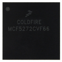
MCF5272CVF66 Freescale Semiconductor, MCF5272CVF66 Datasheet - Page 252

MCF5272CVF66
Manufacturer Part Number
MCF5272CVF66
Description
IC MPU 32BIT 66MHZ 196-MAPBGA
Manufacturer
Freescale Semiconductor
Series
MCF527xr
Specifications of MCF5272CVF66
Core Processor
Coldfire V2
Core Size
32-Bit
Speed
66MHz
Connectivity
EBI/EMI, Ethernet, I²C, SPI, UART/USART, USB
Peripherals
DMA, WDT
Number Of I /o
32
Program Memory Size
16KB (4K x 32)
Program Memory Type
ROM
Ram Size
1K x 32
Voltage - Supply (vcc/vdd)
3 V ~ 3.6 V
Oscillator Type
External
Operating Temperature
-40°C ~ 85°C
Package / Case
196-MAPBGA
Family Name
MCF5xxx
Device Core
ColdFire
Device Core Size
32b
Frequency (max)
66MHz
Instruction Set Architecture
RISC
Supply Voltage 1 (typ)
3.3V
Operating Temp Range
-40C to 85C
Operating Temperature Classification
Industrial
Mounting
Surface Mount
Pin Count
196
Package Type
MA-BGA
Lead Free Status / RoHS Status
Contains lead / RoHS non-compliant
Eeprom Size
-
Data Converters
-
Lead Free Status / Rohs Status
Not Compliant
Available stocks
Company
Part Number
Manufacturer
Quantity
Price
Company:
Part Number:
MCF5272CVF66
Manufacturer:
Freescale Semiconductor
Quantity:
10 000
Part Number:
MCF5272CVF66
Manufacturer:
FREESCALE
Quantity:
20 000
Company:
Part Number:
MCF5272CVF66 K75N
Manufacturer:
ST
Quantity:
18
Company:
Part Number:
MCF5272CVF66J
Manufacturer:
Freescale Semiconductor
Quantity:
10 000
- Current page: 252 of 544
- Download datasheet (7Mb)
Ethernet Module
11.5.24 FEC Initialization
In the FEC, the descriptor control machine initializes a few registers whenever the ETHER_EN control is
asserted. The transmit and receive FIFO pointers are reset, the transmit backoff random number is
initialized, and the transmit and receive blocks are activated. After the FEC initialization sequence is
complete, the hardware is ready for operation, waiting for RDAR and TDAR to be asserted by the user.
11.5.24.1 User Initialization (after setting ETHER_EN)
The user initializes portions of the FEC after setting ETHER_EN. The exact values depend on the
particular application. The sequence probably resembles the steps shown in
could also be done before asserting ETHER_EN.
11.6
Data associated with the FEC controller is stored in buffers, which are referenced by buffer descriptors
(BDs) organized as tables in the dual-port RAM. These tables have the same basic configuration as those
used by the USB.
The BD table allows users to define separate buffers for transmission and reception. Each table forms a
circular queue, or ring. The FEC uses status and control fields in the BDs to inform the core that the buffers
have been serviced, to confirm reception and transmission events, or to indicate error conditions.
11-34
Buffer Descriptors
Table 11-32. User Initialization Process (before ETHER_EN) (continued)
Step
Step
10
11
12
13
14
15
MCF5272 ColdFire
7
8
9
1
2
Table 11-33. User Initialization (after ETHER_EN)
®
Integrated Microprocessor User’s Manual, Rev. 3
Fill Receive Descriptor Ring with Empty Buffers
Initialize (Empty) RxBD
Initialize (Empty) TxBD
Set HTUR and HTLR
Set MSCR (optional)
Description
Description
Set EMRBR
Set ERDSR
Set ETDSR
Set RDAR
Set RCR
Set TCR
Table
11-33, though these
Freescale Semiconductor
Related parts for MCF5272CVF66
Image
Part Number
Description
Manufacturer
Datasheet
Request
R
Part Number:
Description:
Mcf5272 Coldfire Integrated Microprocessor User
Manufacturer:
Freescale Semiconductor, Inc
Datasheet:

Part Number:
Description:
MCF5272 Interrupt Service Routine for the Physical Layer Interface Controller
Manufacturer:
Freescale Semiconductor / Motorola
Datasheet:
Part Number:
Description:
Manufacturer:
Freescale Semiconductor, Inc
Datasheet:
Part Number:
Description:
Manufacturer:
Freescale Semiconductor, Inc
Datasheet:
Part Number:
Description:
Manufacturer:
Freescale Semiconductor, Inc
Datasheet:
Part Number:
Description:
Manufacturer:
Freescale Semiconductor, Inc
Datasheet:
Part Number:
Description:
Manufacturer:
Freescale Semiconductor, Inc
Datasheet:
Part Number:
Description:
Manufacturer:
Freescale Semiconductor, Inc
Datasheet:
Part Number:
Description:
Manufacturer:
Freescale Semiconductor, Inc
Datasheet:
Part Number:
Description:
Manufacturer:
Freescale Semiconductor, Inc
Datasheet:
Part Number:
Description:
Manufacturer:
Freescale Semiconductor, Inc
Datasheet:
Part Number:
Description:
Manufacturer:
Freescale Semiconductor, Inc
Datasheet:
Part Number:
Description:
Manufacturer:
Freescale Semiconductor, Inc
Datasheet:
Part Number:
Description:
Manufacturer:
Freescale Semiconductor, Inc
Datasheet:
Part Number:
Description:
Manufacturer:
Freescale Semiconductor, Inc
Datasheet:


