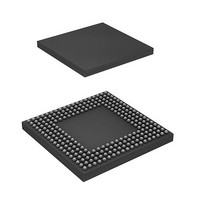
HD6417727BP100BV Renesas Electronics America, HD6417727BP100BV Datasheet - Page 55

HD6417727BP100BV
Manufacturer Part Number
HD6417727BP100BV
Description
IC SUPERH MPU ROMLESS 240BGA
Manufacturer
Renesas Electronics America
Series
SuperH® SH7700r
Datasheet
1.HD6417727BP100CV.pdf
(1098 pages)
Specifications of HD6417727BP100BV
Core Processor
SH-3 DSP
Core Size
32-Bit
Speed
100MHz
Connectivity
FIFO, SCI, SIO, SmartCard, USB
Peripherals
DMA, LCD, POR, WDT
Number Of I /o
104
Program Memory Type
ROMless
Ram Size
32K x 8
Voltage - Supply (vcc/vdd)
1.6 V ~ 2.05 V
Data Converters
A/D 6x10b; D/A 2x8b
Oscillator Type
Internal
Operating Temperature
-20°C ~ 75°C
Package / Case
240-BGA
Lead Free Status / RoHS Status
Contains lead / RoHS non-compliant
Eeprom Size
-
Program Memory Size
-
- Current page: 55 of 1098
- Download datasheet (7Mb)
Table 18.3
Table 18.4
Table 18.5
Table 18.6
Table 18.7
Table 18.8
Table 18.9
Section 19 Serial Communication Interface with FIFO (SCIF)
Table 19.1
Table 19.2
Table 19.3
Table 19.4
Table 19.5
Table 19.6
Table 19.7
Table 19.8
Table 19.9
Section 20 Serial IO (SIOF)
Table 20.1
Table 20.2
Table 20.3
Table 20.4
Table 20.5
Table 20.6
Table 20.7
Table 20.8
Table 20.9
Table 20.10 Receive Request Submit Condition........................................................................ 640
Table 20.11 Transmit or Receive Reset ..................................................................................... 645
Table 20.12 SIOF Interrupt Factors............................................................................................ 646
Table 20.13 Setting Conditions for the Transmit or Receive Interrupt Flag .............................. 647
Section 21 Analog Front End Interface (AFEIF)
Table 21.1
Table 21.2
Table 21.3
Register Settings for the Smart Card Interface ....................................................... 551
Relationship of n to CKS1 and CKS0 .................................................................... 553
Examples of Bit Rate B (Bit/s) for SCBRR Settings (n = 0).................................. 553
Examples of SCBRR Settings for Bit Rate B (Bit/s) (n = 0).................................. 553
Maximum Bit Rates for Frequencies (Smart Card Interface Mode)....................... 554
Register Set Values and SCK0 Pin......................................................................... 554
Smart Card Mode Operating State and Interrupt Sources ...................................... 561
SCIF Pins ............................................................................................................... 568
Registers................................................................................................................. 569
SCSMR2 Settings................................................................................................... 581
Bit Rates and SCBRR2 Settings............................................................................. 581
Maximum Bit Rates for Various Frequencies with Baud Rate Generator
(Asynchronous Mode)............................................................................................ 585
SCSMR2 Settings and SCIF Transmit/Receive ..................................................... 589
Settings for SCSMR2 and SCSCR2 and Selection of Clock Source of SCIF ........ 590
Serial Transmit/Receive Formats ........................................................................... 590
SCIF Interrupt Sources........................................................................................... 600
SIOF Pin List.......................................................................................................... 607
SIOF Register Configuration.................................................................................. 607
Examples of SIOF Clock Frequency...................................................................... 630
Serial Transmit Mode............................................................................................. 632
Frame Length ......................................................................................................... 633
Transmit Data Sound Mode ................................................................................... 635
Receive Data Sound Mode ..................................................................................... 635
Control Data Channel Number Establishment ....................................................... 636
Transmit Request Submit Condition ...................................................................... 639
Pins for AFE Interface............................................................................................ 659
AFEIF Registers..................................................................................................... 659
Telephone Number and Data.................................................................................. 669
Rev.6.00 Mar. 27, 2009 Page liii of lvi
REJ09B0254-0600
Related parts for HD6417727BP100BV
Image
Part Number
Description
Manufacturer
Datasheet
Request
R

Part Number:
Description:
KIT STARTER FOR M16C/29
Manufacturer:
Renesas Electronics America
Datasheet:

Part Number:
Description:
KIT STARTER FOR R8C/2D
Manufacturer:
Renesas Electronics America
Datasheet:

Part Number:
Description:
R0K33062P STARTER KIT
Manufacturer:
Renesas Electronics America
Datasheet:

Part Number:
Description:
KIT STARTER FOR R8C/23 E8A
Manufacturer:
Renesas Electronics America
Datasheet:

Part Number:
Description:
KIT STARTER FOR R8C/25
Manufacturer:
Renesas Electronics America
Datasheet:

Part Number:
Description:
KIT STARTER H8S2456 SHARPE DSPLY
Manufacturer:
Renesas Electronics America
Datasheet:

Part Number:
Description:
KIT STARTER FOR R8C38C
Manufacturer:
Renesas Electronics America
Datasheet:

Part Number:
Description:
KIT STARTER FOR R8C35C
Manufacturer:
Renesas Electronics America
Datasheet:

Part Number:
Description:
KIT STARTER FOR R8CL3AC+LCD APPS
Manufacturer:
Renesas Electronics America
Datasheet:

Part Number:
Description:
KIT STARTER FOR RX610
Manufacturer:
Renesas Electronics America
Datasheet:

Part Number:
Description:
KIT STARTER FOR R32C/118
Manufacturer:
Renesas Electronics America
Datasheet:

Part Number:
Description:
KIT DEV RSK-R8C/26-29
Manufacturer:
Renesas Electronics America
Datasheet:

Part Number:
Description:
KIT STARTER FOR SH7124
Manufacturer:
Renesas Electronics America
Datasheet:

Part Number:
Description:
KIT STARTER FOR H8SX/1622
Manufacturer:
Renesas Electronics America
Datasheet:

Part Number:
Description:
KIT DEV FOR SH7203
Manufacturer:
Renesas Electronics America
Datasheet:


