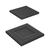
HD6417727BP100BV Renesas Electronics America, HD6417727BP100BV Datasheet - Page 197

HD6417727BP100BV
Manufacturer Part Number
HD6417727BP100BV
Description
IC SUPERH MPU ROMLESS 240BGA
Manufacturer
Renesas Electronics America
Series
SuperH® SH7700r
Datasheet
1.HD6417727BP100CV.pdf
(1098 pages)
Specifications of HD6417727BP100BV
Core Processor
SH-3 DSP
Core Size
32-Bit
Speed
100MHz
Connectivity
FIFO, SCI, SIO, SmartCard, USB
Peripherals
DMA, LCD, POR, WDT
Number Of I /o
104
Program Memory Type
ROMless
Ram Size
32K x 8
Voltage - Supply (vcc/vdd)
1.6 V ~ 2.05 V
Data Converters
A/D 6x10b; D/A 2x8b
Oscillator Type
Internal
Operating Temperature
-20°C ~ 75°C
Package / Case
240-BGA
Lead Free Status / RoHS Status
Contains lead / RoHS non-compliant
Eeprom Size
-
Program Memory Size
-
- Current page: 197 of 1098
- Download datasheet (7Mb)
4.4
4.4.1
The reset sequence is used to power up or restart the SH7727 from the initialization state. The
RESETP and RESETM signals are sampled every clock cycle, and in the case of a power-on reset,
all processing being executed (excluding the RTC) is suspended, all unfinished events are
canceled, and reset processing is executed immediately. In the case of a manual reset, however,
processing to retain external memory contents is continued. The reset sequence consists of the
following operations:
1. The MD bit in SR is set to 1 to place the SH7727 in privileged mode.
2. The BL bit in SR is set to 1, masking any subsequent exceptions (except NMI interrupt when
3. The RB bit in SR is set to 1.
4. An encoded value of H'000 in a power-on reset or H'020 in a manual reset is written to bits 11
5. Instruction execution jumps to the user-written exception handler at address H'A0000000.
4.4.2
An interrupt processing request is accepted on completion of the current instruction. The interrupt
acceptance sequence consists of the following operations:
1. The contents of the PC and SR are saved in SPC and SSR, respectively.
2. The BL bit in SR is set to 1, masking any subsequent exceptions (except NMI interrupt when
3. The MD bit in SR is set to 1 to place the SH7727 in privileged mode.
4. The RB bit in SR is set to 1.
5. An encoded value identifying the exception event is written to bits 11 to 0 of the INTEVT and
0:
imm:
EXPEVT register, INTEVT and INTEVT2 registers
31
0
BLMSK bit is 1).
to 0 of the EXPEVT register to identify the exception event.
BLMSK bit is 1).
INTEVT2 registers.
Figure 4.3 Bit Configurations of EXPEVT, INTEVT, INTEVT2, and TRA Registers
Reserved bits, always read as zero
8-bit immediate data in TRAPA instruction
Exception Handling Operation
Reset
Interrupts
0 Exception code
11
0
TRA register
31
0
Rev.6.00 Mar. 27, 2009 Page 139 of 1036
Section 4 Exception Handling
REJ09B0254-0600
0
9
imm
2 0
00
Related parts for HD6417727BP100BV
Image
Part Number
Description
Manufacturer
Datasheet
Request
R

Part Number:
Description:
KIT STARTER FOR M16C/29
Manufacturer:
Renesas Electronics America
Datasheet:

Part Number:
Description:
KIT STARTER FOR R8C/2D
Manufacturer:
Renesas Electronics America
Datasheet:

Part Number:
Description:
R0K33062P STARTER KIT
Manufacturer:
Renesas Electronics America
Datasheet:

Part Number:
Description:
KIT STARTER FOR R8C/23 E8A
Manufacturer:
Renesas Electronics America
Datasheet:

Part Number:
Description:
KIT STARTER FOR R8C/25
Manufacturer:
Renesas Electronics America
Datasheet:

Part Number:
Description:
KIT STARTER H8S2456 SHARPE DSPLY
Manufacturer:
Renesas Electronics America
Datasheet:

Part Number:
Description:
KIT STARTER FOR R8C38C
Manufacturer:
Renesas Electronics America
Datasheet:

Part Number:
Description:
KIT STARTER FOR R8C35C
Manufacturer:
Renesas Electronics America
Datasheet:

Part Number:
Description:
KIT STARTER FOR R8CL3AC+LCD APPS
Manufacturer:
Renesas Electronics America
Datasheet:

Part Number:
Description:
KIT STARTER FOR RX610
Manufacturer:
Renesas Electronics America
Datasheet:

Part Number:
Description:
KIT STARTER FOR R32C/118
Manufacturer:
Renesas Electronics America
Datasheet:

Part Number:
Description:
KIT DEV RSK-R8C/26-29
Manufacturer:
Renesas Electronics America
Datasheet:

Part Number:
Description:
KIT STARTER FOR SH7124
Manufacturer:
Renesas Electronics America
Datasheet:

Part Number:
Description:
KIT STARTER FOR H8SX/1622
Manufacturer:
Renesas Electronics America
Datasheet:

Part Number:
Description:
KIT DEV FOR SH7203
Manufacturer:
Renesas Electronics America
Datasheet:


