MC9S12NE64VTU Freescale Semiconductor, MC9S12NE64VTU Datasheet - Page 498
MC9S12NE64VTU
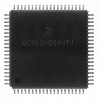
Manufacturer Part Number
MC9S12NE64VTU
Description
IC MCU 25MHZ ETHERNET/PHY 80TQFP
Manufacturer
Freescale Semiconductor
Series
HCS12r
Datasheet
1.MC9S12NE64VTU.pdf
(554 pages)
Specifications of MC9S12NE64VTU
Mfg Application Notes
MC9S12NE64 Integrated Ethernet Controller Implementing an Ethernet Interface with the MC9S12NE64 Web Server Development with MC9S12NE64 and Open TCP
Core Processor
HCS12
Core Size
16-Bit
Speed
25MHz
Connectivity
EBI/EMI, Ethernet, I²C, SCI, SPI
Peripherals
POR, PWM, WDT
Number Of I /o
38
Program Memory Size
64KB (64K x 8)
Program Memory Type
FLASH
Ram Size
8K x 8
Voltage - Supply (vcc/vdd)
2.375 V ~ 3.465 V
Data Converters
A/D 8x10b
Oscillator Type
Internal
Operating Temperature
-40°C ~ 105°C
Package / Case
80-TQFP Exposed Pad, 80-eTQFP, 80-HTQFP, 80-VQFP
Data Bus Width
16 bit
Data Ram Size
8 KB
Interface Type
I2C, SCI, SPI
Maximum Clock Frequency
25 MHz
Number Of Programmable I/os
70
Number Of Timers
16 bit
Operating Supply Voltage
- 0.3 V to + 3 V
Maximum Operating Temperature
+ 105 C
Mounting Style
SMD/SMT
Minimum Operating Temperature
- 65 C
On-chip Adc
10 bit
For Use With
EVB9S12NE64E - BOARD EVAL FOR 9S12NE64DEMO9S12NE64E - DEMO BOARD FOR 9S12NE64
Lead Free Status / RoHS Status
Lead free / RoHS Compliant
Eeprom Size
-
Lead Free Status / Rohs Status
Details
Available stocks
Company
Part Number
Manufacturer
Quantity
Price
Company:

Part Number:
MC9S12NE64VTU
Manufacturer:
FREESCALE
Quantity:
1 831
Company:
Part Number:
MC9S12NE64VTU
Manufacturer:
Freescale Semiconductor
Quantity:
10 000
Company:
Part Number:
MC9S12NE64VTUE
Manufacturer:
Freescale Semiconductor
Quantity:
10 000
Part Number:
MC9S12NE64VTUE
Manufacturer:
FREESCALE
Quantity:
20 000


Chapter 18 Debug Module (DBGV1)
the trigger is at the address of a change-of-flow address the trigger event will not be stored in the trace
buffer.
18.4.2.9
The data stored in the trace buffer can be read using either the background debug module (BDM) module
or the CPU provided the DBG module is enabled and not armed. The trace buffer data is read out first-in
first-out. By reading CNT in DBGCNT the number of valid words can be determined. CNT will not
decrement as data is read from DBGTBH:DBGTBL. The trace buffer data is read by reading
DBGTBH:DBGTBL with a 16-bit read. Each time DBGTBH:DBGTBL is read, a pointer in the DBG will
be incremented to allow reading of the next word.
Reading the trace buffer while the DBG module is armed will return invalid data and no shifting of the
RAM pointer will occur.
18.4.3
There are two ways of getting a breakpoint in DBG mode. One is based on the trigger condition of the
trigger mode using comparator A and/or B, and the other is using comparator C. External breakpoints
generated using the TAGHI and TAGLO external pins are disabled in DBG mode.
18.4.3.1
A breakpoint request to the CPU can be enabled by setting DBGBRK in DBGC1. The value of BEGIN in
DBGC1 determines when the breakpoint request to the CPU will occur. When BEGIN in DBGC1 is set,
begin-trigger is selected and the breakpoint request will not occur until the trace buffer is filled with
64 words. When BEGIN in DBGC1 is cleared, end-trigger is selected and the breakpoint request will occur
immediately at the trigger cycle.
There are two types of breakpoint requests supported by the DBG module, tagged and forced. Tagged
breakpoints are associated with opcode addresses and allow breaking just before a specific instruction
executes. Forced breakpoints are not associated with opcode addresses and allow breaking at the next
instruction boundary. The type of breakpoint based on comparators A and B is determined by TRGSEL in
the DBGC1 register (TRGSEL = 1 for tagged breakpoint, TRGSEL = 0 for forced breakpoint).
Table 18-26
498
Breakpoints
illustrates the type of breakpoint that will occur based on the debug run.
Reading Data from Trace Buffer
Breakpoint Based on Comparator A and B
The trace buffer should be read with the DBG module enabled and in the
same capture mode that the data was recorded. The contents of the trace
buffer counter register (DBGCNT) are resolved differently in detail mode
verses the other modes and may lead to incorrect interpretation of the trace
buffer data.
MC9S12NE64 Data Sheet, Rev. 1.1
NOTE
Freescale Semiconductor
Related parts for MC9S12NE64VTU
Image
Part Number
Description
Manufacturer
Datasheet
Request
R

Part Number:
Description:
Manufacturer:
Freescale Semiconductor, Inc
Datasheet:
Part Number:
Description:
Manufacturer:
Freescale Semiconductor, Inc
Datasheet:
Part Number:
Description:
Manufacturer:
Freescale Semiconductor, Inc
Datasheet:
Part Number:
Description:
Manufacturer:
Freescale Semiconductor, Inc
Datasheet:
Part Number:
Description:
Manufacturer:
Freescale Semiconductor, Inc
Datasheet:
Part Number:
Description:
Manufacturer:
Freescale Semiconductor, Inc
Datasheet:
Part Number:
Description:
Manufacturer:
Freescale Semiconductor, Inc
Datasheet:
Part Number:
Description:
Manufacturer:
Freescale Semiconductor, Inc
Datasheet:
Part Number:
Description:
Manufacturer:
Freescale Semiconductor, Inc
Datasheet:
Part Number:
Description:
Manufacturer:
Freescale Semiconductor, Inc
Datasheet:
Part Number:
Description:
Manufacturer:
Freescale Semiconductor, Inc
Datasheet:
Part Number:
Description:
Manufacturer:
Freescale Semiconductor, Inc
Datasheet:
Part Number:
Description:
Manufacturer:
Freescale Semiconductor, Inc
Datasheet:
Part Number:
Description:
Manufacturer:
Freescale Semiconductor, Inc
Datasheet:
Part Number:
Description:
Manufacturer:
Freescale Semiconductor, Inc
Datasheet: