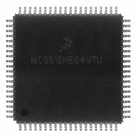
MC9S12NE64VTU Freescale Semiconductor, MC9S12NE64VTU Datasheet - Page 476

MC9S12NE64VTU
Manufacturer Part Number
MC9S12NE64VTU
Description
IC MCU 25MHZ ETHERNET/PHY 80TQFP
Manufacturer
Freescale Semiconductor
Series
HCS12r
Datasheet
1.MC9S12NE64VTU.pdf
(554 pages)
Specifications of MC9S12NE64VTU
Mfg Application Notes
MC9S12NE64 Integrated Ethernet Controller Implementing an Ethernet Interface with the MC9S12NE64 Web Server Development with MC9S12NE64 and Open TCP
Core Processor
HCS12
Core Size
16-Bit
Speed
25MHz
Connectivity
EBI/EMI, Ethernet, I²C, SCI, SPI
Peripherals
POR, PWM, WDT
Number Of I /o
38
Program Memory Size
64KB (64K x 8)
Program Memory Type
FLASH
Ram Size
8K x 8
Voltage - Supply (vcc/vdd)
2.375 V ~ 3.465 V
Data Converters
A/D 8x10b
Oscillator Type
Internal
Operating Temperature
-40°C ~ 105°C
Package / Case
80-TQFP Exposed Pad, 80-eTQFP, 80-HTQFP, 80-VQFP
Data Bus Width
16 bit
Data Ram Size
8 KB
Interface Type
I2C, SCI, SPI
Maximum Clock Frequency
25 MHz
Number Of Programmable I/os
70
Number Of Timers
16 bit
Operating Supply Voltage
- 0.3 V to + 3 V
Maximum Operating Temperature
+ 105 C
Mounting Style
SMD/SMT
Minimum Operating Temperature
- 65 C
On-chip Adc
10 bit
For Use With
EVB9S12NE64E - BOARD EVAL FOR 9S12NE64DEMO9S12NE64E - DEMO BOARD FOR 9S12NE64
Lead Free Status / RoHS Status
Lead free / RoHS Compliant
Eeprom Size
-
Lead Free Status / Rohs Status
Details
Available stocks
Company
Part Number
Manufacturer
Quantity
Price
Company:
Part Number:
MC9S12NE64VTU
Manufacturer:
FREESCALE
Quantity:
1 831
Company:
Part Number:
MC9S12NE64VTU
Manufacturer:
Freescale Semiconductor
Quantity:
10 000
Company:
Part Number:
MC9S12NE64VTUE
Manufacturer:
Freescale Semiconductor
Quantity:
10 000
Part Number:
MC9S12NE64VTUE
Manufacturer:
FREESCALE
Quantity:
20 000
- Current page: 476 of 554
- Download datasheet (4Mb)
Chapter 18 Debug Module (DBGV1)
18.3.2.1
476
TRGSEL
DBGEN
Reset
BEGIN
Field
ARM
7
6
5
4
W
R
DBGEN
DBG Mode Enable Bit — The DBGEN bit enables the DBG module for use in DBG mode. This bit cannot be
set if the MCU is in secure mode.
0 DBG mode disabled
1 DBG mode enabled
Arm Bit — The ARM bit controls whether the debugger is comparing and storing data in the trace buffer. See
Section 18.4.2.4, “Arming the DBG
0 Debugger unarmed
1 Debugger armed
Note: This bit cannot be set if the DBGEN bit is not also being set at the same time. For example, a write of 01
Trigger Selection Bit — The TRGSEL bit controls the triggering condition for comparators A and B in DBG
mode. It serves essentially the same function as the TAGAB bit in the DBGC2 register does in BKP mode. See
Section 18.4.2.1.2, “Trigger
based on comparator A and B if enabled in DBG mode (DBGBRK = 1). Please refer to
“Breakpoint Based on Comparator A and
0 Trigger on any compare address match
1 Trigger before opcode at compare address gets executed (tagged-type)
Begin/End Trigger Bit — The BEGIN bit controls whether the trigger begins or ends storing of data in the trace
buffer. See
for more details.
0 Trigger at end of stored data
1 Trigger before storing data
Debug Control Register 1 (DBGC1)
0
7
All bits are used in DBG mode only.
This register cannot be written if BKP mode is enabled (BKABEN in
DBGC2 is set).
to DBGEN[7:6] will be interpreted as a write of 00.
= Unimplemented or Reserved
Section 18.4.2.8.1, “Storing with
ARM
0
6
Figure 18-4. Debug Control Register (DBGC1)
Table 18-3. DBGC1 Field Descriptions
TRGSEL
Selection,” for more information. TRGSEL may also determine the type of breakpoint
MC9S12NE64 Data Sheet, Rev. 1.1
0
5
Module,” for more information.
B.”
BEGIN
NOTE
NOTE
Begin-Trigger,” and
0
4
Description
DBGBRK
0
3
Section 18.4.2.8.2, “Storing with
0
0
2
Freescale Semiconductor
Section 18.4.3.1,
0
1
CAPMOD
End-Trigger,”
0
0
Related parts for MC9S12NE64VTU
Image
Part Number
Description
Manufacturer
Datasheet
Request
R
Part Number:
Description:
Manufacturer:
Freescale Semiconductor, Inc
Datasheet:
Part Number:
Description:
Manufacturer:
Freescale Semiconductor, Inc
Datasheet:
Part Number:
Description:
Manufacturer:
Freescale Semiconductor, Inc
Datasheet:
Part Number:
Description:
Manufacturer:
Freescale Semiconductor, Inc
Datasheet:
Part Number:
Description:
Manufacturer:
Freescale Semiconductor, Inc
Datasheet:
Part Number:
Description:
Manufacturer:
Freescale Semiconductor, Inc
Datasheet:
Part Number:
Description:
Manufacturer:
Freescale Semiconductor, Inc
Datasheet:
Part Number:
Description:
Manufacturer:
Freescale Semiconductor, Inc
Datasheet:
Part Number:
Description:
Manufacturer:
Freescale Semiconductor, Inc
Datasheet:
Part Number:
Description:
Manufacturer:
Freescale Semiconductor, Inc
Datasheet:
Part Number:
Description:
Manufacturer:
Freescale Semiconductor, Inc
Datasheet:
Part Number:
Description:
Manufacturer:
Freescale Semiconductor, Inc
Datasheet:
Part Number:
Description:
Manufacturer:
Freescale Semiconductor, Inc
Datasheet:
Part Number:
Description:
Manufacturer:
Freescale Semiconductor, Inc
Datasheet:
Part Number:
Description:
Manufacturer:
Freescale Semiconductor, Inc
Datasheet:


