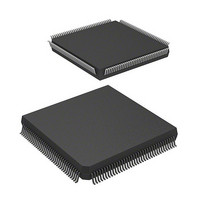
DF2505FC26V Renesas Electronics America, DF2505FC26V Datasheet - Page 44

DF2505FC26V
Manufacturer Part Number
DF2505FC26V
Description
IC H8S/2505 MCU FLASH 144QFP
Manufacturer
Renesas Electronics America
Series
H8® H8S/2500r
Specifications of DF2505FC26V
Core Processor
H8S/2000
Core Size
16-Bit
Speed
26MHz
Connectivity
I²C, SCI
Peripherals
POR, PWM, WDT
Number Of I /o
104
Program Memory Size
384KB (384K x 8)
Program Memory Type
FLASH
Ram Size
32K x 8
Voltage - Supply (vcc/vdd)
3 V ~ 5.5 V
Data Converters
A/D 16x10b; D/A 2x8b
Oscillator Type
Internal
Operating Temperature
-40°C ~ 85°C
Package / Case
144-QFP
Lead Free Status / RoHS Status
Lead free / RoHS Compliant
Eeprom Size
-
- Current page: 44 of 980
- Download datasheet (6Mb)
Table 5.3
Table 5.4
Table 5.5
Table 5.6
Table 5.7
Table 5.8
Table 5.9
Section 7 Bus Controller
Table 7.1
Table 7.2
Table 7.3
Table 7.4
Table 7.5
Section 8 Data Transfer Controller (DTC)
Table 8.1
Table 8.2
Table 8.3
Table 8.4
Table 8.5
Table 8.6
Table 8.7
Section 9 I/O Ports
Table 9.1
Table 9.2
Table 9.3
Table 9.4
Table 9.5
Table 9.6
Table 9.7
Section 10 16-Bit Timer Pulse Unit (TPU)
Table 10.1
Table 10.2
Table 10.3
Table 10.4
Table 10.5
Table 10.6
Rev. 6.00 Sep. 24, 2009 Page xlii of xlvi
REJ09B0099-0600
Interrupt Control Modes.......................................................................................... 100
Interrupts Selected in Each Interrupt Control Mode (1).......................................... 102
Interrupts Selected in Each Interrupt Control Mode (2).......................................... 102
Operations and Control Signal Functions in Each Interrupt Control Mode ............ 103
Interrupt Response Times (States) .......................................................................... 109
Number of States in Interrupt Handling Routine Execution Status......................... 110
Interrupt Source Selection and Clear Control ......................................................... 112
Pin Configuration .................................................................................................... 125
Bus Specifications for Each Area (Basic Bus Interface)......................................... 136
Data Buses Used and Valid Strobes ........................................................................ 146
Pin States in Idle Cycle ........................................................................................... 162
Pin States in Bus Mastership Released State........................................................... 163
Activation Source and DTCER Clearing ................................................................ 175
Interrupt Sources, DTC Vector Addresses, and Corresponding DTCEs................. 178
Register Function in Normal Mode......................................................................... 182
Register Function in Repeat Mode.......................................................................... 183
Register Function in Block Transfer Mode............................................................. 184
DTC Execution Status............................................................................................. 188
Number of States Required for Each Execution Status........................................... 188
Port Functions ......................................................................................................... 194
Input Pull-Up MOS States (Port A) ........................................................................ 232
Input Pull-Up MOS States (Port B)......................................................................... 238
Input Pull-Up MOS States (Port C)......................................................................... 242
Input Pull-Up MOS States (Port D) ........................................................................ 246
Input Pull-Up MOS States (Port E)......................................................................... 250
Examples of Ways to Handle Unused Input Pins.................................................... 265
TPU Functions ........................................................................................................ 268
TPU Pins ................................................................................................................. 271
CCLR0 to CCLR2 (channels 0 and 3)..................................................................... 277
CCLR0 to CCLR2 (channels 1, 2, 4, and 5)............................................................ 277
TPSC0 to TPSC2 (channel 0).................................................................................. 278
TPSC0 to TPSC2 (channel 1).................................................................................. 278
Related parts for DF2505FC26V
Image
Part Number
Description
Manufacturer
Datasheet
Request
R

Part Number:
Description:
KIT STARTER FOR M16C/29
Manufacturer:
Renesas Electronics America
Datasheet:

Part Number:
Description:
KIT STARTER FOR R8C/2D
Manufacturer:
Renesas Electronics America
Datasheet:

Part Number:
Description:
R0K33062P STARTER KIT
Manufacturer:
Renesas Electronics America
Datasheet:

Part Number:
Description:
KIT STARTER FOR R8C/23 E8A
Manufacturer:
Renesas Electronics America
Datasheet:

Part Number:
Description:
KIT STARTER FOR R8C/25
Manufacturer:
Renesas Electronics America
Datasheet:

Part Number:
Description:
KIT STARTER H8S2456 SHARPE DSPLY
Manufacturer:
Renesas Electronics America
Datasheet:

Part Number:
Description:
KIT STARTER FOR R8C38C
Manufacturer:
Renesas Electronics America
Datasheet:

Part Number:
Description:
KIT STARTER FOR R8C35C
Manufacturer:
Renesas Electronics America
Datasheet:

Part Number:
Description:
KIT STARTER FOR R8CL3AC+LCD APPS
Manufacturer:
Renesas Electronics America
Datasheet:

Part Number:
Description:
KIT STARTER FOR RX610
Manufacturer:
Renesas Electronics America
Datasheet:

Part Number:
Description:
KIT STARTER FOR R32C/118
Manufacturer:
Renesas Electronics America
Datasheet:

Part Number:
Description:
KIT DEV RSK-R8C/26-29
Manufacturer:
Renesas Electronics America
Datasheet:

Part Number:
Description:
KIT STARTER FOR SH7124
Manufacturer:
Renesas Electronics America
Datasheet:

Part Number:
Description:
KIT STARTER FOR H8SX/1622
Manufacturer:
Renesas Electronics America
Datasheet:

Part Number:
Description:
KIT DEV FOR SH7203
Manufacturer:
Renesas Electronics America
Datasheet:


