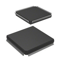
DF2505FC26V Renesas Electronics America, DF2505FC26V Datasheet - Page 39

DF2505FC26V
Manufacturer Part Number
DF2505FC26V
Description
IC H8S/2505 MCU FLASH 144QFP
Manufacturer
Renesas Electronics America
Series
H8® H8S/2500r
Specifications of DF2505FC26V
Core Processor
H8S/2000
Core Size
16-Bit
Speed
26MHz
Connectivity
I²C, SCI
Peripherals
POR, PWM, WDT
Number Of I /o
104
Program Memory Size
384KB (384K x 8)
Program Memory Type
FLASH
Ram Size
32K x 8
Voltage - Supply (vcc/vdd)
3 V ~ 5.5 V
Data Converters
A/D 16x10b; D/A 2x8b
Oscillator Type
Internal
Operating Temperature
-40°C ~ 85°C
Package / Case
144-QFP
Lead Free Status / RoHS Status
Lead free / RoHS Compliant
Eeprom Size
-
- Current page: 39 of 980
- Download datasheet (6Mb)
Figure 20.3 Flash Memory Configuration .................................................................................. 671
Figure 20.4 Block Division of User MAT.................................................................................. 672
Figure 20.5 Overview of User Procedure Program .................................................................... 673
Figure 20.6 System Configuration in Boot Mode....................................................................... 699
Figure 20.7 Automatic-Bit-Rate Adjustment Operation of SCI ................................................. 700
Figure 20.8 Overview of Boot Mode State Transition Diagram................................................. 702
Figure 20.9 Programming/Erasing Overview Flow.................................................................... 703
Figure 20.10 RAM Map when Programming/Erasing Is Executed .............................................. 704
Figure 20.11 Programming Procedure.......................................................................................... 705
Figure 20.12 Erasing Procedure ................................................................................................... 711
Figure 20.13 Sample Procedure of Repeating RAM Emulation, Erasing, and Programming
Figure 20.14 Procedure for Programming User MAT in User Boot Mode .................................. 715
Figure 20.15 Procedure for Erasing User MAT in User Boot Mode ............................................ 717
Figure 20.16 Transitions to Error-Protection State....................................................................... 728
Figure 20.17 Emulation of Flash Memory in RAM ..................................................................... 729
Figure 20.18 Example of a RAM-Overlap Operation .................................................................. 730
Figure 20.19 Programming of the Data after Tuning ................................................................... 731
Figure 20.20 Switching between the User MAT and User Boot MAT ........................................ 732
Figure 20.21 On-Chip Flash Memory Map .................................................................................. 734
Figure 20.22 Pin arrangement of Socket Adapter......................................................................... 735
Figure 20.23 Boot Program States................................................................................................ 742
Figure 20.24 Bit-Rate-Adjustment Sequence ............................................................................... 743
Figure 20.25 Communication Protocol Format ............................................................................ 744
Figure 20.26 New Bit-Rate Selection Sequence........................................................................... 754
Figure 20.27 Programming Sequence........................................................................................... 758
Figure 20.28 Erasure Sequence .................................................................................................... 761
Figure 20.29 Memory Read Timing after Command Programming ............................................ 767
Figure 20.30 Waveform of Transition from Memory-Read Mode to Other Mode....................... 768
Figure 20.31 Waveform of CE, OE Enable State Read................................................................ 769
Figure 20.32 Waveform of CE, OE Clock System Read.............................................................. 769
Figure 20.33 Waveform of Automatic Programming Mode......................................................... 770
Figure 20.34 Waveform in Auto-Erase Mode .............................................................................. 771
Figure 20.35 Waveform in Status-Read Mode ............................................................................. 772
Figure 20.36 Oscillation Stabilized Time, Programmer Mode Setup Time and Power Falling
Section 21 Clock Pulse Generator
Figure 21.1 Block Diagram of Clock Pulse Generator ............................................................... 775
Figure 21.2 Connection of Crystal Resonator (Example)........................................................... 780
(Overview) .............................................................................................................. 713
Sequence ................................................................................................................. 773
Rev. 6.00 Sep. 24, 2009 Page xxxvii of xlvi
REJ09B0099-0600
Related parts for DF2505FC26V
Image
Part Number
Description
Manufacturer
Datasheet
Request
R

Part Number:
Description:
KIT STARTER FOR M16C/29
Manufacturer:
Renesas Electronics America
Datasheet:

Part Number:
Description:
KIT STARTER FOR R8C/2D
Manufacturer:
Renesas Electronics America
Datasheet:

Part Number:
Description:
R0K33062P STARTER KIT
Manufacturer:
Renesas Electronics America
Datasheet:

Part Number:
Description:
KIT STARTER FOR R8C/23 E8A
Manufacturer:
Renesas Electronics America
Datasheet:

Part Number:
Description:
KIT STARTER FOR R8C/25
Manufacturer:
Renesas Electronics America
Datasheet:

Part Number:
Description:
KIT STARTER H8S2456 SHARPE DSPLY
Manufacturer:
Renesas Electronics America
Datasheet:

Part Number:
Description:
KIT STARTER FOR R8C38C
Manufacturer:
Renesas Electronics America
Datasheet:

Part Number:
Description:
KIT STARTER FOR R8C35C
Manufacturer:
Renesas Electronics America
Datasheet:

Part Number:
Description:
KIT STARTER FOR R8CL3AC+LCD APPS
Manufacturer:
Renesas Electronics America
Datasheet:

Part Number:
Description:
KIT STARTER FOR RX610
Manufacturer:
Renesas Electronics America
Datasheet:

Part Number:
Description:
KIT STARTER FOR R32C/118
Manufacturer:
Renesas Electronics America
Datasheet:

Part Number:
Description:
KIT DEV RSK-R8C/26-29
Manufacturer:
Renesas Electronics America
Datasheet:

Part Number:
Description:
KIT STARTER FOR SH7124
Manufacturer:
Renesas Electronics America
Datasheet:

Part Number:
Description:
KIT STARTER FOR H8SX/1622
Manufacturer:
Renesas Electronics America
Datasheet:

Part Number:
Description:
KIT DEV FOR SH7203
Manufacturer:
Renesas Electronics America
Datasheet:


