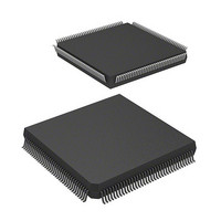
DF2505FC26V Renesas Electronics America, DF2505FC26V Datasheet - Page 14

DF2505FC26V
Manufacturer Part Number
DF2505FC26V
Description
IC H8S/2505 MCU FLASH 144QFP
Manufacturer
Renesas Electronics America
Series
H8® H8S/2500r
Specifications of DF2505FC26V
Core Processor
H8S/2000
Core Size
16-Bit
Speed
26MHz
Connectivity
I²C, SCI
Peripherals
POR, PWM, WDT
Number Of I /o
104
Program Memory Size
384KB (384K x 8)
Program Memory Type
FLASH
Ram Size
32K x 8
Voltage - Supply (vcc/vdd)
3 V ~ 5.5 V
Data Converters
A/D 16x10b; D/A 2x8b
Oscillator Type
Internal
Operating Temperature
-40°C ~ 85°C
Package / Case
144-QFP
Lead Free Status / RoHS Status
Lead free / RoHS Compliant
Eeprom Size
-
- Current page: 14 of 980
- Download datasheet (6Mb)
Section 7 Bus Controller ..................................................................................... 123
7.1
7.2
7.3
7.4
7.5
7.6
7.7
7.8
7.9
7.10 Bus Arbitration .................................................................................................................. 165
Rev. 6.00 Sep. 24, 2009 Page xii of xlvi
REJ09B0099-0600
6.4.5
6.4.6
6.4.7
6.4.8
Features.............................................................................................................................. 123
Input/Output Pins............................................................................................................... 125
Register Descriptions......................................................................................................... 125
7.3.1
7.3.2
7.3.3
7.3.4
7.3.5
7.3.6
Bus Control........................................................................................................................ 134
7.4.1
7.4.2
7.4.3
7.4.4
Basic Timing...................................................................................................................... 139
7.5.1
7.5.2
7.5.3
Basic Bus Interface ............................................................................................................ 145
7.6.1
7.6.2
7.6.3
7.6.4
Burst ROM Interface ......................................................................................................... 157
7.7.1
7.7.2
Idle Cycle........................................................................................................................... 160
Bus Release........................................................................................................................ 163
7.9.1
7.10.1 Operation .............................................................................................................. 165
7.10.2 Bus Mastership Transfer Timing .......................................................................... 165
PC Break Set for Instruction Fetch at Address Following BSR, JSR, JMP, TRAPA,
RTE, or RTS Instruction....................................................................................... 121
I Bit Set by LDC, ANDC, ORC, or XORC Instruction ........................................ 121
PC Break Set for Instruction Fetch at Address Following Bcc Instruction........... 122
PC Break Set for Instruction Fetch at Branch Destination Address of Bcc
Instruction............................................................................................................. 122
Bus Width Control Register (ABWCR) ............................................................... 126
Access State Control Register (ASTCR) .............................................................. 126
Wait Control Registers H and L (WCRH, WCRL)............................................... 127
Bus Control Register H (BCRH) .......................................................................... 130
Bus Control Register L (BCRL) ........................................................................... 131
Pin Function Control Register (PFCR) ................................................................. 132
Area Divisions ...................................................................................................... 134
Bus Specifications ................................................................................................ 135
Bus Interface for Each Area.................................................................................. 136
Chip Select Signals ............................................................................................... 137
On-Chip Memory (ROM, RAM) Access Timing ................................................. 139
On-Chip Peripheral Module Access Timing......................................................... 140
External Address Space Access Timing ............................................................... 144
Data Size and Data Alignment.............................................................................. 145
Valid Strobes ........................................................................................................ 146
Basic Timing......................................................................................................... 147
Wait Control ......................................................................................................... 155
Basic Timing......................................................................................................... 157
Wait Control ......................................................................................................... 159
Usage Note for Bus Mastership Release............................................................... 164
Related parts for DF2505FC26V
Image
Part Number
Description
Manufacturer
Datasheet
Request
R

Part Number:
Description:
KIT STARTER FOR M16C/29
Manufacturer:
Renesas Electronics America
Datasheet:

Part Number:
Description:
KIT STARTER FOR R8C/2D
Manufacturer:
Renesas Electronics America
Datasheet:

Part Number:
Description:
R0K33062P STARTER KIT
Manufacturer:
Renesas Electronics America
Datasheet:

Part Number:
Description:
KIT STARTER FOR R8C/23 E8A
Manufacturer:
Renesas Electronics America
Datasheet:

Part Number:
Description:
KIT STARTER FOR R8C/25
Manufacturer:
Renesas Electronics America
Datasheet:

Part Number:
Description:
KIT STARTER H8S2456 SHARPE DSPLY
Manufacturer:
Renesas Electronics America
Datasheet:

Part Number:
Description:
KIT STARTER FOR R8C38C
Manufacturer:
Renesas Electronics America
Datasheet:

Part Number:
Description:
KIT STARTER FOR R8C35C
Manufacturer:
Renesas Electronics America
Datasheet:

Part Number:
Description:
KIT STARTER FOR R8CL3AC+LCD APPS
Manufacturer:
Renesas Electronics America
Datasheet:

Part Number:
Description:
KIT STARTER FOR RX610
Manufacturer:
Renesas Electronics America
Datasheet:

Part Number:
Description:
KIT STARTER FOR R32C/118
Manufacturer:
Renesas Electronics America
Datasheet:

Part Number:
Description:
KIT DEV RSK-R8C/26-29
Manufacturer:
Renesas Electronics America
Datasheet:

Part Number:
Description:
KIT STARTER FOR SH7124
Manufacturer:
Renesas Electronics America
Datasheet:

Part Number:
Description:
KIT STARTER FOR H8SX/1622
Manufacturer:
Renesas Electronics America
Datasheet:

Part Number:
Description:
KIT DEV FOR SH7203
Manufacturer:
Renesas Electronics America
Datasheet:


