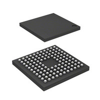
DF2214BQ16V Renesas Electronics America, DF2214BQ16V Datasheet - Page 35

DF2214BQ16V
Manufacturer Part Number
DF2214BQ16V
Description
IC H8S/2214 MCU FLASH 112-TFBGA
Manufacturer
Renesas Electronics America
Series
H8® H8S/2200r
Datasheets
1.HS2214ECB62H.pdf
(938 pages)
2.HEWH8E10A.pdf
(19 pages)
3.D12312SVTE25V.pdf
(341 pages)
Specifications of DF2214BQ16V
Core Processor
H8S/2000
Core Size
16-Bit
Speed
16MHz
Connectivity
SCI
Peripherals
DMA, POR, PWM, WDT
Number Of I /o
72
Program Memory Size
128KB (128K x 8)
Program Memory Type
FLASH
Ram Size
12K x 8
Voltage - Supply (vcc/vdd)
2.7 V ~ 3.6 V
Data Converters
D/A 1x8b
Oscillator Type
Internal
Operating Temperature
-20°C ~ 75°C
Package / Case
112-TFBGA
For Use With
HS0005KCU11H - EMULATOR E10A-USB H8S(X),SH2(A)3DK2218 - DEV EVAL KIT H8S/2218
Lead Free Status / RoHS Status
Lead free / RoHS Compliant
Eeprom Size
-
Available stocks
Company
Part Number
Manufacturer
Quantity
Price
Company:
Part Number:
DF2214BQ16V
Manufacturer:
Renesas Electronics America
Quantity:
10 000
- Current page: 35 of 938
- Download datasheet (6Mb)
4.4
4.5
4.6
4.7
Section 5 Interrupt Controller ............................................................................. 91
5.1
5.2
5.3
5.4
5.5
5.6
Interrupts .............................................................................................................................. 87
Trap Instruction.................................................................................................................... 88
Stack Status after Exception Handling................................................................................. 89
Notes on Use of the Stack .................................................................................................... 90
Overview.............................................................................................................................. 91
5.1.1
5.1.2
5.1.3
5.1.4
Register Descriptions ........................................................................................................... 94
5.2.1
5.2.2
5.2.3
5.2.4
5.2.5
Interrupt Sources .................................................................................................................. 99
5.3.1
5.3.2
5.3.3
Interrupt Operation............................................................................................................. 104
5.4.1
5.4.2
5.4.3
5.4.4
5.4.5
Usage Notes ....................................................................................................................... 113
5.5.1
5.5.2
5.5.3
5.5.4
5.5.5
5.5.6
DTC and DMAC Activation by Interrupt .......................................................................... 116
5.6.1
5.6.2
5.6.3
Features................................................................................................................... 91
Block Diagram ........................................................................................................ 92
Pin Configuration.................................................................................................... 93
Register Configuration............................................................................................ 93
System Control Register (SYSCR) ......................................................................... 94
Interrupt Priority Registers A to D, F, G, J, K, M
(IPRA to IPRD, IPRF, IPRG, IPRJ, IPRK, IPRM)................................................. 95
IRQ Enable Register (IER) ..................................................................................... 96
IRQ Sense Control Registers H and L (ISCRH, ISCRL)........................................ 97
IRQ Status Register (ISR)....................................................................................... 98
External Interrupts .................................................................................................. 99
Internal Interrupts.................................................................................................. 101
Interrupt Exception Handling Vector Table.......................................................... 101
Interrupt Control Modes and Interrupt Operation ................................................. 104
Interrupt Control Mode 0 ...................................................................................... 107
Interrupt Control Mode 2 ...................................................................................... 109
Interrupt Exception Handling Sequence ............................................................... 111
Interrupt Response Times ..................................................................................... 112
Contention between Interrupt Generation and Disabling...................................... 113
Instructions that Disable Interrupts ....................................................................... 114
Times when Interrupts Are Disabled .................................................................... 114
Interrupts during Execution of EEPMOV Instruction........................................... 115
IRQ Interrupts ....................................................................................................... 115
NMI Interrupt Usage Notes................................................................................... 115
Overview............................................................................................................... 116
Block Diagram ...................................................................................................... 116
Operation .............................................................................................................. 117
Rev.4.00 Sep. 18, 2008 Page xxxiii of lx
REJ09B0189-0400
Related parts for DF2214BQ16V
Image
Part Number
Description
Manufacturer
Datasheet
Request
R

Part Number:
Description:
CONN SOCKET 2POS 7.92MM WHITE
Manufacturer:
Hirose Electric Co Ltd
Datasheet:

Part Number:
Description:
CONN SOCKET 4POS 7.92MM WHITE
Manufacturer:
Hirose Electric Co Ltd
Datasheet:

Part Number:
Description:
CONN SOCKET 5POS 7.92MM WHITE
Manufacturer:
Hirose Electric Co Ltd
Datasheet:

Part Number:
Description:
CONN SOCKET 3POS 7.92MM WHITE
Manufacturer:
Hirose Electric Co Ltd
Datasheet:

Part Number:
Description:
CONN SOCKET 5POS 7.92MM WHITE
Manufacturer:
Hirose Electric Co Ltd
Datasheet:

Part Number:
Description:
CONN SOCKET 2POS 7.92MM WHITE
Manufacturer:
Hirose Electric Co Ltd
Datasheet:

Part Number:
Description:
CONN SOCKET 3POS 7.92MM WHITE
Manufacturer:
Hirose Electric Co Ltd
Datasheet:

Part Number:
Description:
CONN SOCKET 4POS 7.92MM WHITE
Manufacturer:
Hirose Electric Co Ltd
Datasheet:

Part Number:
Description:
CONN HEADER 2POS 7.92MM R/A TIN
Manufacturer:
Hirose Electric Co Ltd
Datasheet:

Part Number:
Description:
CONN HEADER 4POS 7.92MM R/A TIN
Manufacturer:
Hirose Electric Co Ltd
Datasheet:

Part Number:
Description:
KIT STARTER FOR M16C/29
Manufacturer:
Renesas Electronics America
Datasheet:

Part Number:
Description:
KIT STARTER FOR R8C/2D
Manufacturer:
Renesas Electronics America
Datasheet:

Part Number:
Description:
R0K33062P STARTER KIT
Manufacturer:
Renesas Electronics America
Datasheet:

Part Number:
Description:
KIT STARTER FOR R8C/23 E8A
Manufacturer:
Renesas Electronics America
Datasheet:

Part Number:
Description:
KIT STARTER FOR R8C/25
Manufacturer:
Renesas Electronics America
Datasheet:


