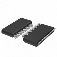
SC28L201A1DGG,118 NXP Semiconductors, SC28L201A1DGG,118 Datasheet - Page 68

SC28L201A1DGG,118
Manufacturer Part Number
SC28L201A1DGG,118
Description
IC UART W/FIFO 48-TSSOP
Manufacturer
NXP Semiconductors
Series
IMPACTr
Datasheet
1.SC28L201A1DGG118.pdf
(110 pages)
Specifications of SC28L201A1DGG,118
Features
False-start Bit Detection
Number Of Channels
2, DUART
Fifo's
256 Byte
Voltage - Supply
3.3V, 5V
With Parallel Port
Yes
With Auto Flow Control
Yes
With False Start Bit Detection
Yes
With Modem Control
Yes
With Cmos
Yes
Mounting Type
Surface Mount
Package / Case
48-TSSOP
Lead Free Status / RoHS Status
Lead free / RoHS Compliant
Other names
935277824118
SC28L201A1DGG-T
SC28L201A1DGG-T
SC28L201A1DGG-T
SC28L201A1DGG-T
Philips Semiconductors
9397 750 13138
Product data sheet
8.4.8 The CTS, RTS, CTS Enable Tx signals
If the value in CTPU and CTPL is changed, the current half-period will not be affected, but
subsequent half-periods will be. The C/T will not be running until it receives an initial
‘Start Counter’ command from the Command Register (or a read at address
A6 to A0 = 0x0E in the lower 16 position address space). After this, while in timer mode,
the C/T will run continuously. Receipt of a start counter command causes the counter to
terminate the current timing cycle and to begin a new cycle using the values in CTPU and
CTPL.
The counter ready status bit (ISR[3]) is set once each cycle of the square wave. The bit is
reset by a stop counter command from the command register (or a read with
A6 to A0 = 0x0F in the lower 16 position address space). The command however, does
not stop the C/T. the generated square wave is output on I/O3 if it is programmed to be the
C/T output. In the counter mode, the value C/T loaded into CTPU and CTPL by the CPU is
counted down to 0. Counting begins upon receipt of a start counter command. Upon
reaching terminal count 0x0000, the counter ready interrupt bit (ISR[3]) is set. The counter
continues counting past the terminal count until stopped by the CPU. If I/O3 is
programmed to be the output of the C/T, the output remains HIGH until terminal count is
reached; at which time it goes LOW. The output returns to the HIGH state and ISR[3] is
cleared when the counter is stopped by a stop counter command. The CPU may change
the values of CTPU and CTPL at any time, but the new count becomes effective only on
the next start counter commands. If new values have not been loaded, the previous count
values are preserved and used for the next count cycle.
In the counter mode, the current value of the upper and lower 8 bits of the counter (CTPU,
CTPL) may be read by the CPU. It is recommended that the counter be stopped when
reading to prevent potential problems that may occur if a carry from the lower 8 bits to the
upper 8 bits occurs between the times that both halves of the counter are read. However,
note that a subsequent start counter command will cause the counter to begin a new
count cycle using the values in CTPU and CTPL. When the C/T clock divided by 16 is
selected, the maximum divisor becomes 1,048,575.
CTS (Clear To Send) is usually meant to be a signal to the transmitter meaning that it may
transmit data to the receiver. The CTS input is on pin I/O0A for Tx A. The CTS signal is
active LOW, thus it is called CTSN A for Tx A. RTS is usually meant to be a signal from
the receiver indicating that the receiver is ready to receive data. It is also active LOW and
is called RTSN A for Rx A. RTSN A is on pin I/O0B. A receiver’s RTSN output will usually
be connected to the CTS input of the associated transmitter. Therefore, one could say that
RTS and CTS are different ends of the same wire!
MR2[4] is the bit that allows the transmitter to be controlled by the CTS pin (I/O0A or
I/O1A). When this bit is set to one and the CTS input is driven HIGH, the transmitter will
stop sending data at the end of the present character being serialized. It is usually the
RTS output of the receiver that will be connected to the transmitter’s CTS input. The
receiver will set RTS HIGH when the receiver FIFO is full and the start bit of the ninth
character is sensed. Transmission then stops with nine valid characters in the receiver.
When MR2[4] is set to one, CTSN must be at zero for the transmitter to operate. If MR2[4]
is set to zero, the I/O pin will have no effect on the operation of the transmitter. MR1[7] is
the bit that allows the receiver to control I/O0B. When the receiver controls I/O0B, the
meaning of that pin will be the RTSN function.
Rev. 01 — 31 October 2005
3.3 V, 5 V UART, 3.125 Mbit/s, with 256-byte FIFO
© Koninklijke Philips Electronics N.V. 2005. All rights reserved.
SC28L201
68 of 110


