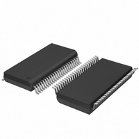
SC28L201A1DGG,118 NXP Semiconductors, SC28L201A1DGG,118 Datasheet - Page 47

SC28L201A1DGG,118
Manufacturer Part Number
SC28L201A1DGG,118
Description
IC UART W/FIFO 48-TSSOP
Manufacturer
NXP Semiconductors
Series
IMPACTr
Datasheet
1.SC28L201A1DGG118.pdf
(110 pages)
Specifications of SC28L201A1DGG,118
Features
False-start Bit Detection
Number Of Channels
2, DUART
Fifo's
256 Byte
Voltage - Supply
3.3V, 5V
With Parallel Port
Yes
With Auto Flow Control
Yes
With False Start Bit Detection
Yes
With Modem Control
Yes
With Cmos
Yes
Mounting Type
Surface Mount
Package / Case
48-TSSOP
Lead Free Status / RoHS Status
Lead free / RoHS Compliant
Other names
935277824118
SC28L201A1DGG-T
SC28L201A1DGG-T
SC28L201A1DGG-T
SC28L201A1DGG-T
Philips Semiconductors
9397 750 13138
Product data sheet
Table 18:
Bit
5
4
3:0
Symbol
MR2 - Mode Register 2 (address 0x22) bit description
Description
Tx Controls RTS. Transmitter Request-to-Send Control.
This bit controls the deactivation of the RTSN output (I/O2) by the transmitter.
This output is manually asserted and negated by appropriate commands
issued via the command register. MR2[5] = 1 negates (drives to logical 1)
RTSN automatically one bit time after the characters in the transmit shift
register and in the TxFIFO (if any) are completely transmitted (includes the
programmed number of stop bits if the transmitter is not enabled). This
feature can be used to automatically terminate the transmission of a
message as follows:
Remark: When the transmitter controls the RTSN pin, the meaning of the pin
is completely changed. It has nothing to do with the normal RTSN/CTSN
‘handshaking’. It is usually used to mean ‘end of message’ and to ‘turn the
line around’ in simplex communications. From a practical point of view, the
simultaneous use of Tx control of RTSN and Rx control is mutually exclusive.
However, if this is programmed, the UART performs as required.
CTS Enable Tx. Clear-to-Send Control.
The state of this bit determines if the CTSN input (I/O0) controls the
operation of the transmitter. If this bit is 0, CTSN has no effect on the
transmitter. If this bit is a 1, the transmitter checks the state of CTSN each
time it is ready to begin sending a character. If it is asserted (LOW), the
character is transmitted. If it is negated (HIGH), the TXD output remains in
the marking state and the transmission is delayed until CTSN goes LOW.
Changes in CTSN, while a character is being transmitted, do not affect the
transmission of that character. This feature can be used to prevent overrun of
a remote receiver.
Please see the CTS description in
description of direct software control of this pin, thus giving software a direct
control of the transmitter.
Stop Bit Length Select.
This field programs the length of the stop bit appended to the transmitted
character. Stop bit lengths of
cases, the receiver only checks for a mark condition at the center of the first
stop bit position (one bit time after the last data bit, or after the parity bit if
parity is enabled). If an external 1 clock is used for the transmitter,
MR2[1] = 0 selects one stop bit and MR2[1] = 1 selects two stop bits to be
transmitted.
•
•
•
•
•
•
Rev. 01 — 31 October 2005
Program Auto Reset mode: MR2[5] = 1.
Enable transmitter.
Assert RTSN via command.
Send message.
Verify the next-to-last character of the message is being sent by waiting
until transmitter ready is asserted. Disable transmitter after the last
character is loaded into the TxFIFO.
The last character will be transmitted and RTSN will be reset one bit
time after the last stop bit.
3.3 V, 5 V UART, 3.125 Mbit/s, with 256-byte FIFO
9
16
bit through 2 bits can be programmed. In all
Section 7.4.6 “Transmitter”
© Koninklijke Philips Electronics N.V. 2005. All rights reserved.
…continued
SC28L201
for a
47 of 110


