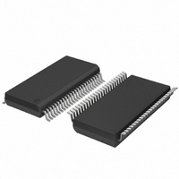
SC28L201A1DGG,118 NXP Semiconductors, SC28L201A1DGG,118 Datasheet - Page 54

SC28L201A1DGG,118
Manufacturer Part Number
SC28L201A1DGG,118
Description
IC UART W/FIFO 48-TSSOP
Manufacturer
NXP Semiconductors
Series
IMPACTr
Datasheet
1.SC28L201A1DGG118.pdf
(110 pages)
Specifications of SC28L201A1DGG,118
Features
False-start Bit Detection
Number Of Channels
2, DUART
Fifo's
256 Byte
Voltage - Supply
3.3V, 5V
With Parallel Port
Yes
With Auto Flow Control
Yes
With False Start Bit Detection
Yes
With Modem Control
Yes
With Cmos
Yes
Mounting Type
Surface Mount
Package / Case
48-TSSOP
Lead Free Status / RoHS Status
Lead free / RoHS Compliant
Other names
935277824118
SC28L201A1DGG-T
SC28L201A1DGG-T
SC28L201A1DGG-T
SC28L201A1DGG-T
Philips Semiconductors
9397 750 13138
Product data sheet
8.2.7 Channel Status Register (SR)
Table 24:
Bit
7
6
5
4
3
Symbol
FE
PE
OE
Tx Idle
SR - Channel Status Register (address 0x01) bit description
Description
Received Break.
This bit indicates that an all zero character (including parity, if used) of the
programmed length has been received with a stop bit at a logical zero. A
single FIFO position is loaded with 0x00 when a break is received; further
entries to the FIFO are inhibited until the RXD line returns to the marking
state for at least one half bit time (two successive edges of the internal or
external 1 clock). When this bit is set, the change in break bit in the ISR
(ISR[2]) is set. ISR[2] is also set when the end of the break condition, as
defined above, is detected. The break detect circuitry is capable of detecting
breaks that originate in the middle of a received character. However, if a
break begins in the middle of a character, it must last until the end of the next
character in order for it to be detected.
Framing Error.
This bit indicates that a stop bit was not detected when an otherwise
non-zeros data character (including parity, if enabled) was received. The
stop bit check is made in the middle of the first stop bit position.
Parity Error.
This bit is set when the ‘with parity’ or ‘force parity’ mode is programmed and
the corresponding character in the FIFO was received with incorrect parity. In
the special Wake-up mode, the parity error bit stores the received A/D bit.
Overrun Error.
This bit, when set, indicates that one or more characters in the received data
stream have been lost. It is set upon receipt of the start bit of a new character
when the RxFIFO is full and a character is already in the receive shift register
(257 valid characters in the receiver) waiting for an empty FIFO position.
When this occurs, the character in the receive shift register (and its break
detect, parity error and framing error status, if any) is lost. This bit is cleared
by a reset error status command.
Transmitter Idle.
This bit is set when the transmitter underruns, that is, both the TxFIFO and
the Transmit Shift Register are empty. It is set after transmission of the last
stop bit of a character, if no character is in the TxFIFO awaiting transmission.
It is negated when the TxFIFO is loaded by the CPU, or when the transmitter
is disabled or reset. This bit is concerned with the transmitter transmitting
data and it essentially shows ‘transmitter underrun’. If, while it is underrun it
is commanded to send an Xon/Xoff character it will remain at the zero state.
If it is underrun and while sending an Xon/Xoff character the TxFIFO is
loaded then the bit will go LOW.
0 = no
1 = yes
0 = no
1 = yes
0 = no
1 = yes
0 = no
1 = yes
0 = no
1 = yes
Rev. 01 — 31 October 2005
3.3 V, 5 V UART, 3.125 Mbit/s, with 256-byte FIFO
© Koninklijke Philips Electronics N.V. 2005. All rights reserved.
SC28L201
54 of 110


