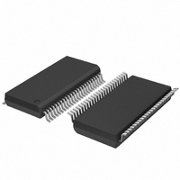
SC28L201A1DGG,118 NXP Semiconductors, SC28L201A1DGG,118 Datasheet - Page 20

SC28L201A1DGG,118
Manufacturer Part Number
SC28L201A1DGG,118
Description
IC UART W/FIFO 48-TSSOP
Manufacturer
NXP Semiconductors
Series
IMPACTr
Datasheet
1.SC28L201A1DGG118.pdf
(110 pages)
Specifications of SC28L201A1DGG,118
Features
False-start Bit Detection
Number Of Channels
2, DUART
Fifo's
256 Byte
Voltage - Supply
3.3V, 5V
With Parallel Port
Yes
With Auto Flow Control
Yes
With False Start Bit Detection
Yes
With Modem Control
Yes
With Cmos
Yes
Mounting Type
Surface Mount
Package / Case
48-TSSOP
Lead Free Status / RoHS Status
Lead free / RoHS Compliant
Other names
935277824118
SC28L201A1DGG-T
SC28L201A1DGG-T
SC28L201A1DGG-T
SC28L201A1DGG-T
Philips Semiconductors
9397 750 13138
Product data sheet
7.4.7 Receiver operation
The TxRDY bit is set whenever the transmitter is enabled and the TxFIFO is not full. Data
is transferred from the holding register to Transmit Shift Register when it is idle or has
completed transmission of the previous character. Characters cannot be loaded into the
TxFIFO while the transmitter is disabled.
The transmitter converts the parallel data from the CPU to a serial bit stream on the TXD
output pin. It automatically sends a start bit followed by the programmed number of data
bits, an optional parity bit, and the programmed number of stop bits. The least significant
bit is sent first. Following the transmission of the stop bits, if a new character is not
available in the TxFIFO, the TXD output remains High and the Tx Idle bit in the Status
Register (SR) will be set to 1. Transmission resumes and the Tx Idle bit is cleared when
the CPU loads a new character into the TxFIFO.
If the transmitter is disabled, it continues operating until the character currently being
transmitted is completely sent out. The transmitter can be forced to send a continuous
LOW condition by issuing a ‘send break’ command. The transmitter can be reset through
a software command. If it is reset, operation ceases immediately and the transmitter must
be enabled through the Command Register before resuming operation.
If CTS option of hardware flow control is enabled (MR2[4] = 1), the CTS input at I/O[0]A
must be LOW in order for the character to be transmitted. The transmitter will check the
state of the CTS input at the beginning of each character transmitted. If it is found to be
HIGH, the transmitter will delay the transmission of any characters until the CTS has
returned to the LOW state. CTS going HIGH during the serialization of a character will not
affect that character.
An interesting result of the I/O pin input circuit always being active is that it gives software
control of transmitter activity. Programming the MR2[4] to ‘1’ gives I/O[0]A (CTSN) control
of the transmitter. Thus, if software drives I/O[0]A HIGH or LOW, the transmission of data
is started or stopped by direct software commands.
The transmitter can also control the RTSN outputs, I/O[0]B, via MR2[5]. When this mode
of operation is set (often referred to as the RS-485 method) the meaning of the I/O[0]B
signal is all bytes loaded to the transmitters FIFO have been transmitted including the last
stop bit(s). See
function.
The receiver accepts serial data on the RXD pin, converts the serial input to parallel
format, checks for start bit, stop bit, parity bit (if any), framing error or break condition, and
presents the assembled character and its status condition to the CPU via the RxFIFO.
Three status bits are FIFOed with each character received. The RxFIFO is really 11 bits
wide: eight data bits and 3 status bits. Unused FIFO bits for character lengths less than
8 bits are set to zero.
It is important to note that in the asynchronous protocol the receiver logic considers the
entire message to be contained within the start bit to the stop bit. It is not aware that a
message may contain many characters. The receiver returns to its Idle mode at the
end of each stop bit. As described below it immediately begins to search for another
start bit, which is normally, of course, immediately forthcoming.
Section 8.2.3 “Mode Register 2 (MR2)”
Rev. 01 — 31 October 2005
3.3 V, 5 V UART, 3.125 Mbit/s, with 256-byte FIFO
for enabling this automatic
© Koninklijke Philips Electronics N.V. 2005. All rights reserved.
SC28L201
20 of 110


