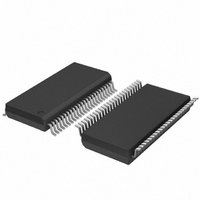
SC28L201A1DGG,118 NXP Semiconductors, SC28L201A1DGG,118 Datasheet - Page 27

SC28L201A1DGG,118
Manufacturer Part Number
SC28L201A1DGG,118
Description
IC UART W/FIFO 48-TSSOP
Manufacturer
NXP Semiconductors
Series
IMPACTr
Datasheet
1.SC28L201A1DGG118.pdf
(110 pages)
Specifications of SC28L201A1DGG,118
Features
False-start Bit Detection
Number Of Channels
2, DUART
Fifo's
256 Byte
Voltage - Supply
3.3V, 5V
With Parallel Port
Yes
With Auto Flow Control
Yes
With False Start Bit Detection
Yes
With Modem Control
Yes
With Cmos
Yes
Mounting Type
Surface Mount
Package / Case
48-TSSOP
Lead Free Status / RoHS Status
Lead free / RoHS Compliant
Other names
935277824118
SC28L201A1DGG-T
SC28L201A1DGG-T
SC28L201A1DGG-T
SC28L201A1DGG-T
Philips Semiconductors
9397 750 13138
Product data sheet
7.4.7.9 Receiver Time-out mode
7.4.8 Arbitrating interrupt structure
Remark: This is similar to the watchdog above, but its more precise meaning is that the
receiver data stream has stopped.
In addition to the watchdog timer described in
used for a similar function. Its programmability, of course, allows much greater precision of
time-out intervals.
The Time-out mode uses the received data stream to control the counter. Each time a
received character is transferred from the shift register to the RxFIFO, the counter is
restarted. If a new character is not received before the counter reaches zero count, the
counter ready bit is set, and an interrupt can be generated. This mode can be used to
indicate when data has been left in the RxFIFO for more than the programmed time limit.
Otherwise, if the receiver has been programmed to interrupt the CPU when the receive
FIFO is full, and the message ends before the FIFO is full, the CPU may not know there is
data left in the FIFO. The CTPU and CTPL value would be programmed for just over
one character time, so that the CPU would be interrupted as soon as it has stopped
receiving continuous data. This mode can also be used to indicate when the serial line
has been marking for longer than the programmed time limit. In this case, the CPU has
read all of the characters from the FIFO, but the last character received has started the
count. If there is no new data during the programmed time interval, the counter ready bit
will get set, and an interrupt can be generated.
Writing the appropriate command to the Command Register enables the Time-out mode.
Writing an ‘Ax’ to CR will invoke the Time-out mode for that channel. Writing a 0xCx to CR
will disable the Time-out mode. CTPU and CTPL should be loaded with a count-down
value that, with the selected clock, will generate a time period greater than the normal
receive character period. The Time-out mode disables the regular START/STOP Counter
commands and puts the C/T into Counter mode under the control of the received data
stream. Each time a received character is transferred from the shift register to the
RxFIFO, the C/T is stopped after 1 C/T clock, reloaded with the value in CTPU and CTPL
and then restarted on the next C/T clock. If the C/T is allowed to end the count before a
new character has been received, the counter ready bit, ISR[3], will be set. If IMR[3] is set,
interrupt arbitration for the C/T will begin. Invoking the ‘Set Time-out Mode On’ command,
CRx = ‘Ax’, clears the counter ready bit and stops the counter until the next character is
received.
Exiting the Time-out mode, CR command 0x0C, will clear the counter ready bit.
Remark: The one or two bus cycle identification of the interrupt source, type, FIFO fill
level, and channel is the principle advantage of this system. It is equally effective in both
interrupt of polled method of UART service. Its most efficient use is with the use of the
interrupt vector and IACKN. IACKN is totally effective in the polled mode. The intelligence
of this system may be completely defeated by merely setting the arbitration value in the
ICR to 0x00 and not using the CIR. One would then rely on traditional interrupt service by
searching and testing various status registers on the chips assertion of IRQN.
The center point of this system is the value contained in Current Interrupt Register (CIR).
This register contains the FIFO byte count, a unique identification number for each
interrupt source and a channel number for multichannel UARTs. The CIR is continuously
Rev. 01 — 31 October 2005
3.3 V, 5 V UART, 3.125 Mbit/s, with 256-byte FIFO
Section
7.4.7.8, the counter/timer may be
© Koninklijke Philips Electronics N.V. 2005. All rights reserved.
SC28L201
27 of 110


