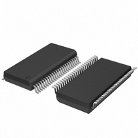
SC28L201A1DGG,118 NXP Semiconductors, SC28L201A1DGG,118 Datasheet - Page 31

SC28L201A1DGG,118
Manufacturer Part Number
SC28L201A1DGG,118
Description
IC UART W/FIFO 48-TSSOP
Manufacturer
NXP Semiconductors
Series
IMPACTr
Datasheet
1.SC28L201A1DGG118.pdf
(110 pages)
Specifications of SC28L201A1DGG,118
Features
False-start Bit Detection
Number Of Channels
2, DUART
Fifo's
256 Byte
Voltage - Supply
3.3V, 5V
With Parallel Port
Yes
With Auto Flow Control
Yes
With False Start Bit Detection
Yes
With Modem Control
Yes
With Cmos
Yes
Mounting Type
Surface Mount
Package / Case
48-TSSOP
Lead Free Status / RoHS Status
Lead free / RoHS Compliant
Other names
935277824118
SC28L201A1DGG-T
SC28L201A1DGG-T
SC28L201A1DGG-T
SC28L201A1DGG-T
Philips Semiconductors
9397 750 13138
Product data sheet
7.4.8.4 IACKN cycle, update CIR
7.4.8.5 Global registers
For example: The break condition is sometimes used to signal a starting point in a
continuous stream of data. A Continuous running weather report or stock market
‘ticker-tape’ report needs breaks in the data so that a receiver knows where the data
starts. Once start of the break is detected it is important to reset the ‘change of break’
interrupt so that this bit can signal the condition of the break ending. This is signaled by
the SC28L201 the setting another change of break event in the ISR. Since it is assumed
the data will be starting very soon after the end of break it is important to give the change
of break condition a high priority. This may be accomplished by setting the arbitration
value for the ‘change of break’ to a high value. The value in the ‘change of break
programmable field’ in
When the host CPU responds to the interrupt, it will usually assert the IACKN signal LOW.
This will cause the UART to generate an IACKN cycle in which the condition of the
interrupting device is determined. When IACKN asserts, the last valid interrupt number is
captured in the CIR. The value captured presents most of the important details of the
highest priority interrupt at the moment the IACKN (or the ‘Update CIR’ command) was
asserted.
The UART will respond to the IACKN cycle with an interrupt vector. The interrupt vector
may be a fixed value, the content of the Interrupt Vector Register, or when ‘Interrupt Vector
Modification’ is enabled via ICR, it may contain codes for the interrupt type and/or
interrupting channel. This allows the interrupt vector to steer the interrupt service directly
to the proper service routine. The interrupt value captured in the CIR remains until another
IACKN cycle occurs or until an ‘Update CIR’ command is given to the UART. The
interrupting channel and interrupt type fields of the CIR set the current ‘interrupt context’
of the UART.
The CIR drives the several Global Interrupt Information registers that appear at fixed
positions in the register address map. For example, a read of the Global Byte Count return
the value of the FIFO fill level of the receiver or transmitter depending on which one is
interrupting. Global registers exist to facilitate qualifying the interrupt parameters and for
writing to and reading from FIFOs without explicitly addressing them. They are essentially
indirect addresses to characteristics of the interrupting source.
The CIR will load with 0x00 if IACKN or Update CIR is asserted when the arbitration circuit
is not asserting an interrupt. In this condition there is no arbitration value that exceeds the
threshold value. When Interrupt vector modification is active in this situation the interrupt
vector bits associated with the CIR will all be zero.
The Global Registers, 10 in all, are driven by the interrupt system. They are defined by the
content of the CIR (Current Interrupt Register) as a result of an interrupt arbitration. In
other words they are indirect registers pointed to by the content of the CIR. The list of
global register follows:
•
•
•
•
GIBCR: the byte count of the interrupting FIFO
GICR: channel number of the interrupting channel
The GCIR will read 0 except for Counter/Timer 1 and I/O[n]B pins
GITR: type identification of interrupting channel
GRxFIFO: pointer to the interrupting receiver FIFO
Rev. 01 — 31 October 2005
Table 4
would be 0x7F.
3.3 V, 5 V UART, 3.125 Mbit/s, with 256-byte FIFO
© Koninklijke Philips Electronics N.V. 2005. All rights reserved.
SC28L201
31 of 110


