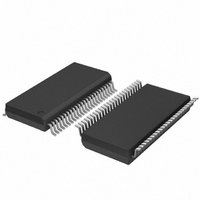
SC28L201A1DGG,118 NXP Semiconductors, SC28L201A1DGG,118 Datasheet - Page 26

SC28L201A1DGG,118
Manufacturer Part Number
SC28L201A1DGG,118
Description
IC UART W/FIFO 48-TSSOP
Manufacturer
NXP Semiconductors
Series
IMPACTr
Datasheet
1.SC28L201A1DGG118.pdf
(110 pages)
Specifications of SC28L201A1DGG,118
Features
False-start Bit Detection
Number Of Channels
2, DUART
Fifo's
256 Byte
Voltage - Supply
3.3V, 5V
With Parallel Port
Yes
With Auto Flow Control
Yes
With False Start Bit Detection
Yes
With Modem Control
Yes
With Cmos
Yes
Mounting Type
Surface Mount
Package / Case
48-TSSOP
Lead Free Status / RoHS Status
Lead free / RoHS Compliant
Other names
935277824118
SC28L201A1DGG-T
SC28L201A1DGG-T
SC28L201A1DGG-T
SC28L201A1DGG-T
Philips Semiconductors
9397 750 13138
Product data sheet
7.4.7.7 Receiver reset and disable
7.4.7.8 Receiver watchdog timer
detect operate normally whether or not the receiver is enabled. When the automatic
modes are in operation the loading of the address character to the FIFO is controlled by
the MR0[6] bit.
The several automatic controls. These modes are concerned with the recognition of the
address character itself:
The enabling of the Wake-up mode executes a partial enabling of the receiver state
machine. Even though the receiver has been reset, the Wake-up mode will override the
disable and reset conditions.
Please note the difference between Receiver disable and reset.
Receiver disable stops the receiver immediately. Data being assembled in the Receiver
Shift Register is lost. Data and status in the FIFO is preserved and may be read. A
re-enable of the receiver after a disable will cause the receiver to begin assembling
characters at the next start bit detected.
Receiver reset will discard the present shift register data, reset the receiver ready bit
(RxRDY), clear the status of the byte at the top of the FIFO and re-align the FIFO
read/write pointers. This effectively clears the receiver FIFO, although the FIFO data is not
altered.
A ‘watchdog timer’ is associated with each receiver. Its interrupt is enabled by the
‘watchdog’ bits of the Watchdog, Character Address, and X enable register (WCXER).
The purpose of this timer is to alert the control processor that characters are in the
RxFIFO which have not been read. This situation may occur at the end of a transmission
when the last few characters received are not sufficient to cause an interrupt. The
Watchdog counter times out after 64 bit times. It is reset each time a read of the RxFIFO is
executed or a write to the RxFIFO is executed by the receiver state machine.
•
•
•
MR3[1:0] = 01; Auto wake.
Enable receiver on address recognition for this station. Upon recognition of its
assigned address the local receiver will be enabled by the character recognition state
machine and normal receiver communications with the host will be established. The
address just received may be discarded (stripped from the data stream) or loaded to
the RxFIFO depending on the programming of MR0[6].
MR3[1:0] = 10; Auto Doze.
Disable receiver on address recognition, not for this station. Upon recognition of an
address character that is not its own, in the Auto Doze mode, the receiver will be
disabled by the character recognition state machine and the address just received
either discarded or loaded to the RxFIFO depending on the programming of MR0[6].
MR3[1:0] = 11; Auto wake and doze.
Both modes described above. The programming of MR3[1:0] to 11 will enable both
the auto wake and auto doze features. The address just received may be discarded
(stripped from the data stream) or loaded to the RxFIFO depending on the
programming of MR0[6].
Rev. 01 — 31 October 2005
3.3 V, 5 V UART, 3.125 Mbit/s, with 256-byte FIFO
© Koninklijke Philips Electronics N.V. 2005. All rights reserved.
SC28L201
26 of 110


