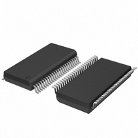
SC28L201A1DGG,118 NXP Semiconductors, SC28L201A1DGG,118 Datasheet - Page 32

SC28L201A1DGG,118
Manufacturer Part Number
SC28L201A1DGG,118
Description
IC UART W/FIFO 48-TSSOP
Manufacturer
NXP Semiconductors
Series
IMPACTr
Datasheet
1.SC28L201A1DGG118.pdf
(110 pages)
Specifications of SC28L201A1DGG,118
Features
False-start Bit Detection
Number Of Channels
2, DUART
Fifo's
256 Byte
Voltage - Supply
3.3V, 5V
With Parallel Port
Yes
With Auto Flow Control
Yes
With False Start Bit Detection
Yes
With Modem Control
Yes
With Cmos
Yes
Mounting Type
Surface Mount
Package / Case
48-TSSOP
Lead Free Status / RoHS Status
Lead free / RoHS Compliant
Other names
935277824118
SC28L201A1DGG-T
SC28L201A1DGG-T
SC28L201A1DGG-T
SC28L201A1DGG-T
Philips Semiconductors
9397 750 13138
Product data sheet
7.4.8.6 Polling (normal and using the CIR)
7.4.9 Character and address recognition (also used for multi-drop, Xon/Xoff
A read of the GRxFIFO will give the content of the RxFIFO that presently has the highest
bid value. The purpose of this system is to enhance the efficiency of the interrupt system.
The ‘arbitrating interrupt system’ will reduce the polling overhead to one or two bus cycles
depending on the use of IACKN. This interrupt system does not need either the IRQN
(interrupt request) or the IACKN (interrupt acknowledge) signal. It only requires an update
CIR command. Recall that if nothing has exceeded preset levels, including 0x00, the CIR
will read 0x00, meaning no service is required. A minimal polling loop would be: update
CIR, read CIR, if 0x00 exit.
Many users prefer polled to interrupt driven service where there are not a large number of
fast data channels and/or the host CPUs other interrupt overhead is low. The UART is
functional in this environment.
The most efficient method of polling is the use of the ‘update CIR’ command (with the
interrupt threshold set to zero) followed by a read of the CIR. This dummy write cycle will
perform the same CIR capture function that an IACKN falling edge would accomplish in an
interrupt driven system. A subsequent read of the CIR, at the same address, will give
information about an interrupt, if any. If the CIR type field contains 0s, no interrupt is
awaiting service. If the value is non-zero, the fields of the CIR may be decoded for type;
channel and character count information. Optionally, the global interrupt registers may be
read for particular information about the interrupt status or use of the global RxD and TXD
registers for data transfer as appropriate. The interrupt context will remain in the CIR until
another update CIR command or an IACKN cycle is initiated by the host CPU occurs. The
CIR loads with 0x00 if Update CIR is asserted when the arbitration circuit has not
detected an arbitration value that exceeds the threshold value of the ICR. The global
registers and CIR may be used as ‘vectors’ to the service type required.
Traditional methods of polling status registers may also be used. Their lower efficiency
may be greatly offset by use of the UCIR (Update Current Interrupt Register) command
and the read of the CIR. They reduce the many reads and tests of status registers to only
one read and one write. This would normally be accomplished by setting the interrupt
threshold to zero. Then the moment any system within the UART needs service the next
poll of the CIR would return a non zero value and the type field will inform the processor
which of the possible 11 systems needs service. In the case of the FIFOs the number of
bytes to be written or read is also available.
systems)
Three programmable characters are provided for the character recognition for each
channel. Each character is general purpose in nature and may be set to only cause an
interrupt or to initiate some rather complex operations specific to ‘multi-drop’ address
recognition or in-band Xon/Xoff flow control.
Character recognition system continually examines the incoming data stream. Upon the
recognition of a character bits appropriate for the character recognized are set in the
Xon/Xoff Interrupt Status Register (XISR) and in the Interrupt Status Register (ISR). The
setting of these bit(s) will initiate any of the automatic sequences or and/or an interrupt
that may have enabled via the MR3 register.
•
GTxFIFO: pointer to the interrupting transmitter FIFO
Rev. 01 — 31 October 2005
3.3 V, 5 V UART, 3.125 Mbit/s, with 256-byte FIFO
© Koninklijke Philips Electronics N.V. 2005. All rights reserved.
SC28L201
32 of 110


