DK-DEV-2AGX125N Altera, DK-DEV-2AGX125N Datasheet - Page 32
DK-DEV-2AGX125N
Manufacturer Part Number
DK-DEV-2AGX125N
Description
KIT DEV ARRIA II GX FPGA 2AGX125
Manufacturer
Altera
Series
Arria II GXr
Type
FPGAr
Datasheets
1.EP2AGX45CU17C6N.pdf
(96 pages)
2.DK-DEV-2AGX125N.pdf
(48 pages)
3.DK-DEV-2AGX125N.pdf
(64 pages)
Specifications of DK-DEV-2AGX125N
Contents
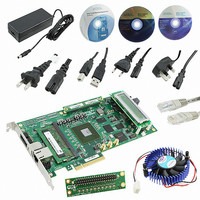
Board, Cables, CD, DVD, Power Supply
Silicon Manufacturer
Altera
Core Architecture
FPGA
Core Sub-architecture
Arria
Silicon Core Number
EP2
Silicon Family Name
Arria II GX
Rohs Compliant
Yes
For Use With/related Products
EP2AGX125EF35
Lead Free Status / RoHS Status
Lead free / RoHS Compliant
Other names
544-2600
Available stocks
Company
Part Number
Manufacturer
Quantity
Price
Company:

Part Number:
DK-DEV-2AGX125N
Manufacturer:
Altera
Quantity:
135


2–24
Table 2–22. Crystal Oscillator Component References and Manufacturing Information
General User Input/Output
Table 2–23. User-defined Push-button Switch Schematic Signal Names and Functions
Arria II GX FPGA Development Board Reference Manual
U25
U26
U30
Y6
Y5
PB2
PB1
PB3
Board Reference
Reference
Board
User-Defined Push-Button Switches
156.25 MHz LVPECL Saw
Oscillator
Quad Output Programmable
Clock Generator
Single Output Programmable
Clock Generator
100 MHz Crystal Oscillator
50 MHz Crystal Oscillator
User-defined push-button switch
Table 2–22
information.
This section describes the user I/O interface to the FPGA, including the push-buttons,
DIP switches, status LEDs, and character LCD.
The development board includes three user-defined push-button switches—two
general user push-button switches and one CPU reset switch. For information on the
system and safe reset push-button switches, refer to
button Switches” on page
Board references PB1 and PB2 are push-button switches that allow you to interact
with the Arria II GX device. When you press and hold the switch, the device pin is set
to logic 0; when you release the switch, the device pin is set to logic 1. There is no
board-specific function for these general user push-button switches.
The board reference PB3 is the CPU reset push-button switch, CPU_RESET, which is an
input to the Arria II GX device. CPU_RESET is intended to be the master reset signal for
the FPGA design loaded into the Arria II GX device. It also acts as a regular I/O pin.
Table 2–23
corresponding Arria II GX device pin numbers.
Description
Description
lists the user-defined push-button switch schematic signal names and their
lists the crystal oscillators component references and manufacturing
Epson
Texas Instruments
Texas Instruments
Mercury Electronics 3H53-AT-100.000
Epson
Manufacturer
2–20.
Schematic Signal
CPU_RESET
USER_PB0
USER_PB1
Name
EG-2102CA
155.5200M-DGPA
CDCM61004RHBR
CDCM61001RHBR
XG-1000CB
50.0000M-DCL3
Manufacturer
Part Number
I/O Standard
“Reset Configuration Push-
1.8-V
2.5-V
February 2011 Altera Corporation
www.eea.epson.com
www.ti.com
www.ti.com
www.mecxtal.com
www.eea.epson.com
Chapter 2: Board Components
Manufacturer Website
General User Input/Output
Arria II GX Device
Pin Number
AK9
N10
AL7
Related parts for DK-DEV-2AGX125N
Image
Part Number
Description
Manufacturer
Datasheet
Request
R

Part Number:
Description:
KIT DEV CYCLONE III LS EP3CLS200
Manufacturer:
Altera
Datasheet:

Part Number:
Description:
KIT DEV STRATIX IV FPGA 4SE530
Manufacturer:
Altera
Datasheet:

Part Number:
Description:
KIT DEV FPGA 2AGX260 W/6.375G TX
Manufacturer:
Altera
Datasheet:

Part Number:
Description:
KIT DEV MAX V 5M570Z
Manufacturer:
Altera
Datasheet:

Part Number:
Description:
KIT DEV STRATIX V FPGA 5SGXEA7
Manufacturer:
Altera
Datasheet:

Part Number:
Description:
KIT DEVELOPMENT STRATIX III
Manufacturer:
Altera
Datasheet:

Part Number:
Description:
KIT DEVELOPMENT STRATIX IV
Manufacturer:
Altera
Datasheet:

Part Number:
Description:
KIT DEV ARRIA GX 1AGX60N
Manufacturer:
Altera
Datasheet:
Part Number:
Description:
KIT STARTER CYCLONE IV GX
Manufacturer:
Altera
Datasheet:
Part Number:
Description:
KIT DEVELOPMENT STRATIX IV
Manufacturer:
Altera
Datasheet:

Part Number:
Description:
CPLD, EP610 Family, ECMOS Process, 300 Gates, 16 Macro Cells, 16 Reg., 16 User I/Os, 5V Supply, 35 Speed Grade, 24DIP
Manufacturer:
Altera Corporation
Datasheet:
Part Number:
Description:
CPLD, EP610 Family, ECMOS Process, 300 Gates, 16 Macro Cells, 16 Reg., 16 User I/Os, 5V Supply, 15 Speed Grade, 24DIP
Manufacturer:
Altera Corporation
Datasheet: