DK-DEV-2AGX125N Altera, DK-DEV-2AGX125N Datasheet - Page 25
DK-DEV-2AGX125N
Manufacturer Part Number
DK-DEV-2AGX125N
Description
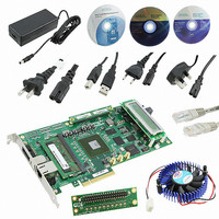
KIT DEV ARRIA II GX FPGA 2AGX125
Manufacturer
Altera
Series
Arria II GXr
Type
FPGAr
Datasheets
1.EP2AGX45CU17C6N.pdf
(96 pages)
2.DK-DEV-2AGX125N.pdf
(48 pages)
3.DK-DEV-2AGX125N.pdf
(64 pages)
Specifications of DK-DEV-2AGX125N
Contents
Board, Cables, CD, DVD, Power Supply
Silicon Manufacturer
Altera
Core Architecture
FPGA
Core Sub-architecture
Arria
Silicon Core Number
EP2
Silicon Family Name
Arria II GX
Rohs Compliant
Yes
For Use With/related Products
EP2AGX125EF35
Lead Free Status / RoHS Status
Lead free / RoHS Compliant
Other names
544-2600
Available stocks
Company
Part Number
Manufacturer
Quantity
Price
Company:

Part Number:
DK-DEV-2AGX125N
Manufacturer:
Altera
Quantity:
135


Chapter 2: Board Components
Configuration, Status, and Setup Elements
Table 2–11. Board-Specific LEDs (Part 1 of 2)
February 2011 Altera Corporation
D18
D14
D15
D16
D11, D12, D13
D19
D20
D23
D22
D21
D6
D1
D24
Board Reference
Status Elements
f
Power
CONF DONE
Loading
Error
CONFIG[2:0]
ENET TX
ENET RX
10
100
1000
HSMC Port A
Present
HSMC Port B
Present
PCIe x1
FPGA Programming over External USB-Blaster
The JTAG programming header provides another method for configuring the FPGA
(U19) using an external USB-Blaster device with the Quartus II Programmer running
on a PC. The external USB-Blaster is connected to the board through the JTAG
connector (J5). Install a shunt onto the JTAG chain header (J9) pins 1 and 2 to remove
the MAX II CPLD device from the JTAG chain so that the FPGA is the only device on
the JTAG chain.
For more information on the following topics, refer to the respective documents:
■
■
■
The development board includes status LEDs. This section describes the status
elements.
Table 2–11
LED Name
Board Update Portal, refer to the
PFL design, refer to the
PFL Megafunction, refer to the
lists the LED board references, names, and functional descriptions.
Blue LED. Illuminates when 2.5 V power is active.
Green LED. Illuminates when the FPGA is successfully configured. Driven by the
MAX II CPLD EPM2210 System Controller.
Green LED. Illuminates when the MAX II CPLD EPM2210 System Controller is
actively configuring the FPGA. Driven by the MAX II CPLD EPM2210 System
Controller wire-OR'd with the embedded USB-Blaster CPLD.
Red LED. Illuminates when the MAX II CPLD EPM2210 System Controller fails to
configure the FPGA. Driven by the MAX II CPLD EPM2210 System Controller.
Green LEDs. Illuminates to indicate which hardware page loads from flash
memory.
Green LED. Illuminates to indicate Ethernet PHY transmit activity. Driven by the
Marvell 88E1111 PHY.
Green LED. Illuminates to indicate Ethernet PHY receive activity. Driven by the
Marvell 88E1111 PHY.
Green LED. Illuminates to indicate Ethernet linked at 10 Mbps connection speed.
Driven by the Marvell 88E1111 PHY.
Green LED. Illuminates to indicate Ethernet linked at 100 Mbps connection speed.
Driven by the Marvell 88E1111 PHY.
Green LED. Illuminates to indicate Ethernet linked at 1000 Mbps connection speed.
Driven by the Marvell 88E1111 PHY.
Green LED. Illuminates when HSMC port A has a board or cable plugged-in such
that pin 160 becomes grounded. Driven by the add-in card.
Green LED. Illuminates when HSMC port B has a board or cable plugged-in such
that pin 160 becomes grounded. Driven by the add-in card.
Green LED. Configure this LED to display the PCI Express link width x1.
Arria II GX FPGA Development Kit User
Parallel Flash Loader Megafunction User
Arria II GX FPGA Development Kit User
Description
Arria II GX FPGA Development Board Reference Manual
Guide.
Guide.
Guide.
2–17
Related parts for DK-DEV-2AGX125N
Image
Part Number
Description
Manufacturer
Datasheet
Request
R

Part Number:
Description:
KIT DEV CYCLONE III LS EP3CLS200
Manufacturer:
Altera
Datasheet:

Part Number:
Description:
KIT DEV STRATIX IV FPGA 4SE530
Manufacturer:
Altera
Datasheet:

Part Number:
Description:
KIT DEV FPGA 2AGX260 W/6.375G TX
Manufacturer:
Altera
Datasheet:

Part Number:
Description:
KIT DEV MAX V 5M570Z
Manufacturer:
Altera
Datasheet:

Part Number:
Description:
KIT DEV STRATIX V FPGA 5SGXEA7
Manufacturer:
Altera
Datasheet:

Part Number:
Description:
KIT DEVELOPMENT STRATIX III
Manufacturer:
Altera
Datasheet:

Part Number:
Description:
KIT DEVELOPMENT STRATIX IV
Manufacturer:
Altera
Datasheet:

Part Number:
Description:
KIT DEV ARRIA GX 1AGX60N
Manufacturer:
Altera
Datasheet:
Part Number:
Description:
KIT STARTER CYCLONE IV GX
Manufacturer:
Altera
Datasheet:
Part Number:
Description:
KIT DEVELOPMENT STRATIX IV
Manufacturer:
Altera
Datasheet:

Part Number:
Description:
CPLD, EP610 Family, ECMOS Process, 300 Gates, 16 Macro Cells, 16 Reg., 16 User I/Os, 5V Supply, 35 Speed Grade, 24DIP
Manufacturer:
Altera Corporation
Datasheet:
Part Number:
Description:
CPLD, EP610 Family, ECMOS Process, 300 Gates, 16 Macro Cells, 16 Reg., 16 User I/Os, 5V Supply, 15 Speed Grade, 24DIP
Manufacturer:
Altera Corporation
Datasheet: