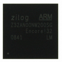
Z32AN00NW200SG Zilog, Z32AN00NW200SG Datasheet - Page 82

Z32AN00NW200SG
Manufacturer Part Number
Z32AN00NW200SG
Description
IC ARM922T MCU 200MHZ 256-BGA
Manufacturer
Zilog
Series
Encore!® 32r
Datasheet
1.Z32AN00NW200SG.pdf
(196 pages)
Specifications of Z32AN00NW200SG
Core Processor
ARM9
Core Size
16/32-Bit
Speed
200MHz
Connectivity
EBI/EMI, IrDA, SmartCard, SPI, UART/USART, USB OTG
Peripherals
DMA, LCD, Magnetic Card Reader, POR, PWM, WDT
Number Of I /o
76
Program Memory Type
ROMless
Ram Size
64K x 8
Voltage - Supply (vcc/vdd)
1.71 V ~ 3.6 V
Data Converters
A/D 4x10b
Oscillator Type
Internal
Operating Temperature
-40°C ~ 85°C
Package / Case
256-LBGA
For Use With
269-4713 - KIT DEV ENCORE 32 SERIES
Lead Free Status / RoHS Status
Lead free / RoHS Compliant
Eeprom Size
-
Program Memory Size
-
Other names
269-4717
Available stocks
Company
Part Number
Manufacturer
Quantity
Price
- Current page: 82 of 196
- Download datasheet (4Mb)
Z32AN Series Data Sheet
Chapter 10: Smart Card Controller
10.1 SPI Interface
10.1.1 Smart Card Controller Interrupt Management
DS0200-003
The Smart Card Controller is an APB device that allows a seamless connection to external Smart Card
Interface devices. Reference to the ON Semiconductor NCN6001 Smart Card Interface IC is made
throughout this chapter which serves as an example interface for the Smart Card Controllers.
The protocol layer is not implemented in hardware and must be managed by the software. The controller
includes the following features:
The SPI port is able to serially send and receive 8-bit data to the external Smart Card Interface IC (MSB
sent and received first). It is a master only interface. The SC_nSS0 and SC_nSS1 determine which external
interface is being accessed.
The clock is active high and idles low. The frequency is programmable through SC_SPI_CLK and allows
discrete division ratios from the hclk frequency: all even numbers between 2 and 32 (inclusive). SPI clock
frequency is calculated as per the below equation:
The SPI data interface comprises of two unidirectional ports: SC_MOSI and SC_MISO. SC_MOSI is an
output serial data line; SC_MISO is a concurrent input serial data line. Data is sent on SC_MOSI and
received from SC_MISO and are clocked by the same clock SC_SCK. Each time a word is sent, another
byte is received.
When the CPU sends a byte through the SPI by writing the data in the SPIDATA register, it can get the
concurrently received byte by reading SPIDATA. The received byte is valid once bit 8 (MSB) of the
SPIDATA is set to 1.
When an automatic RST or VCCON command is sent through the SPI (after a change of one of the 2 Card
Reset or Card VCC lines), a byte is received, which is thrown away. This byte cannot be read by the
processor as SPIDATA is not updated with this data.
Figure 10-1 shows the waveforms of the SPI port. The SC_MISO input is sampled on the falling edge of
SC_SCK, for example, OnSemi Smart Card interface chip (OnSemi NCN6001), must be programmed to
operate in Special Mode. Refer to the datasheet for the OnSemi NCN6001 device or the specific device
used in the application to determine SPI interface requirements.
An Interrupt indicates when an over current, overheating, card removal, or card insertion is detected on one
of the Smart Card interfaces through SC_nALARM. Status is obtained by polling the Smart Card device.
Supports two interfaces: One for maincard and one for SIM card.
Interrupt.
DMA support.
Master only SPI Interface
Programmable Baud Rate Generator.
Timing Checker.
Figure 10-1: SPI Data Transfer
Page 69
Related parts for Z32AN00NW200SG
Image
Part Number
Description
Manufacturer
Datasheet
Request
R

Part Number:
Description:
Communication Controllers, ZILOG INTELLIGENT PERIPHERAL CONTROLLER (ZIP)
Manufacturer:
Zilog, Inc.
Datasheet:

Part Number:
Description:
KIT DEV FOR Z8 ENCORE 16K TO 64K
Manufacturer:
Zilog
Datasheet:

Part Number:
Description:
KIT DEV Z8 ENCORE XP 28-PIN
Manufacturer:
Zilog
Datasheet:

Part Number:
Description:
DEV KIT FOR Z8 ENCORE 8K/4K
Manufacturer:
Zilog
Datasheet:

Part Number:
Description:
KIT DEV Z8 ENCORE XP 28-PIN
Manufacturer:
Zilog
Datasheet:

Part Number:
Description:
DEV KIT FOR Z8 ENCORE 4K TO 8K
Manufacturer:
Zilog
Datasheet:

Part Number:
Description:
CMOS Z8 microcontroller. ROM 16 Kbytes, RAM 256 bytes, speed 16 MHz, 32 lines I/O, 3.0V to 5.5V
Manufacturer:
Zilog, Inc.
Datasheet:

Part Number:
Description:
Low-cost microcontroller. 512 bytes ROM, 61 bytes RAM, 8 MHz
Manufacturer:
Zilog, Inc.
Datasheet:

Part Number:
Description:
Z8 4K OTP Microcontroller
Manufacturer:
Zilog, Inc.
Datasheet:

Part Number:
Description:
CMOS SUPER8 ROMLESS MCU
Manufacturer:
Zilog, Inc.
Datasheet:

Part Number:
Description:
SL1866 CMOSZ8 OTP Microcontroller
Manufacturer:
Zilog, Inc.
Datasheet:

Part Number:
Description:
SL1866 CMOSZ8 OTP Microcontroller
Manufacturer:
Zilog, Inc.
Datasheet:

Part Number:
Description:
OTP (KB) = 1, RAM = 125, Speed = 12, I/O = 14, 8-bit Timers = 2, Comm Interfaces Other Features = Por, LV Protect, Voltage = 4.5-5.5V
Manufacturer:
Zilog, Inc.
Datasheet:

Part Number:
Description:
Manufacturer:
Zilog, Inc.
Datasheet:


