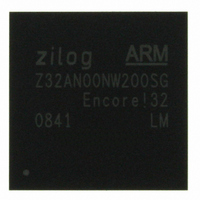
Z32AN00NW200SG Zilog, Z32AN00NW200SG Datasheet - Page 76

Z32AN00NW200SG
Manufacturer Part Number
Z32AN00NW200SG
Description
IC ARM922T MCU 200MHZ 256-BGA
Manufacturer
Zilog
Series
Encore!® 32r
Datasheet
1.Z32AN00NW200SG.pdf
(196 pages)
Specifications of Z32AN00NW200SG
Core Processor
ARM9
Core Size
16/32-Bit
Speed
200MHz
Connectivity
EBI/EMI, IrDA, SmartCard, SPI, UART/USART, USB OTG
Peripherals
DMA, LCD, Magnetic Card Reader, POR, PWM, WDT
Number Of I /o
76
Program Memory Type
ROMless
Ram Size
64K x 8
Voltage - Supply (vcc/vdd)
1.71 V ~ 3.6 V
Data Converters
A/D 4x10b
Oscillator Type
Internal
Operating Temperature
-40°C ~ 85°C
Package / Case
256-LBGA
For Use With
269-4713 - KIT DEV ENCORE 32 SERIES
Lead Free Status / RoHS Status
Lead free / RoHS Compliant
Eeprom Size
-
Program Memory Size
-
Other names
269-4717
Available stocks
Company
Part Number
Manufacturer
Quantity
Price
- Current page: 76 of 196
- Download datasheet (4Mb)
Z32AN Series Data Sheet
9.2.7
9.2.7.1
9.2.7.2
9.2.8
9.2.8.1
9.2.8.2
DS0200-003
Any of the three tracks can be used to generate raw ADC data. There are two means of accessing raw ADC
samples and these are outlined below.
This method has the following advantages and restrictions:
Following are the registers and fields that must be configured to enable use of the MCR_AUX_ADC. Once
configured, every new sample from the configured track is moved into MCR_AUX_ADC (provided that the
previous sample has been read).
This method has the following advantages and restrictions:
Below are the registers and fields that are used to configure a track for ADC mode. Once configured, ADC
samples are streamed into the FIFO along with data from any other enabled channels.
The MCR provides a stream of either delta time or ADC samples. The optimum parameters are strongly
dependent upon system design. Some general guidelines are provided below.
The ADC sample rate is configured by programming MCR_ADC. The sample rate for each track is
dependent upon the number of active channels. The equation to determine the ADC divider is:
For example, if hclk is 90MHz, the number of active MCR channels is 3, and the desired track sample rate is
250kHz, then:
Thus, programming 7 into MCR_ADC.DIV produces a sample rate of 250kHz for each track.
The DC offset needs to be programmed for each track by writing to the MCRn_DCO. To determine value to
use, the programmer should acquire a number of raw ADC samples and choose the average value. The DC
offset should be close to the middle range of 800h. The variation between samples should be less than 00Fh
Acquiring Raw ADC Samples
Programming Guide
Using the Auxiliary ADC Register
Using ADC Mode
Sample Rate Programming
DC Offset Programming
Only one track can be sampled at a time.
The track can be sampled while peak detection mode is active.
There is no FIFO to hold data and DMA is not supported for this register, so response time is
more restricted.
MCR_ADC → All fields
MCR_CTRL → AUX_ADC_IEN, IENn
MCR_AUX_ADC → NEW, SAMPLE, OFLO
Any number of tracks can be sampled at a time.
Peak-Detection must be disabled while a track is in ADC mode.
There is FIFO and DMA support.
MCR_ADC → All fields
MCR_CTRL → MODEn, IENn
MCR_FIFO → TRACK, TIME
Page 63
Related parts for Z32AN00NW200SG
Image
Part Number
Description
Manufacturer
Datasheet
Request
R

Part Number:
Description:
Communication Controllers, ZILOG INTELLIGENT PERIPHERAL CONTROLLER (ZIP)
Manufacturer:
Zilog, Inc.
Datasheet:

Part Number:
Description:
KIT DEV FOR Z8 ENCORE 16K TO 64K
Manufacturer:
Zilog
Datasheet:

Part Number:
Description:
KIT DEV Z8 ENCORE XP 28-PIN
Manufacturer:
Zilog
Datasheet:

Part Number:
Description:
DEV KIT FOR Z8 ENCORE 8K/4K
Manufacturer:
Zilog
Datasheet:

Part Number:
Description:
KIT DEV Z8 ENCORE XP 28-PIN
Manufacturer:
Zilog
Datasheet:

Part Number:
Description:
DEV KIT FOR Z8 ENCORE 4K TO 8K
Manufacturer:
Zilog
Datasheet:

Part Number:
Description:
CMOS Z8 microcontroller. ROM 16 Kbytes, RAM 256 bytes, speed 16 MHz, 32 lines I/O, 3.0V to 5.5V
Manufacturer:
Zilog, Inc.
Datasheet:

Part Number:
Description:
Low-cost microcontroller. 512 bytes ROM, 61 bytes RAM, 8 MHz
Manufacturer:
Zilog, Inc.
Datasheet:

Part Number:
Description:
Z8 4K OTP Microcontroller
Manufacturer:
Zilog, Inc.
Datasheet:

Part Number:
Description:
CMOS SUPER8 ROMLESS MCU
Manufacturer:
Zilog, Inc.
Datasheet:

Part Number:
Description:
SL1866 CMOSZ8 OTP Microcontroller
Manufacturer:
Zilog, Inc.
Datasheet:

Part Number:
Description:
SL1866 CMOSZ8 OTP Microcontroller
Manufacturer:
Zilog, Inc.
Datasheet:

Part Number:
Description:
OTP (KB) = 1, RAM = 125, Speed = 12, I/O = 14, 8-bit Timers = 2, Comm Interfaces Other Features = Por, LV Protect, Voltage = 4.5-5.5V
Manufacturer:
Zilog, Inc.
Datasheet:

Part Number:
Description:
Manufacturer:
Zilog, Inc.
Datasheet:


