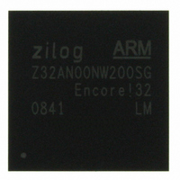
Z32AN00NW200SG Zilog, Z32AN00NW200SG Datasheet - Page 188

Z32AN00NW200SG
Manufacturer Part Number
Z32AN00NW200SG
Description
IC ARM922T MCU 200MHZ 256-BGA
Manufacturer
Zilog
Series
Encore!® 32r
Datasheet
1.Z32AN00NW200SG.pdf
(196 pages)
Specifications of Z32AN00NW200SG
Core Processor
ARM9
Core Size
16/32-Bit
Speed
200MHz
Connectivity
EBI/EMI, IrDA, SmartCard, SPI, UART/USART, USB OTG
Peripherals
DMA, LCD, Magnetic Card Reader, POR, PWM, WDT
Number Of I /o
76
Program Memory Type
ROMless
Ram Size
64K x 8
Voltage - Supply (vcc/vdd)
1.71 V ~ 3.6 V
Data Converters
A/D 4x10b
Oscillator Type
Internal
Operating Temperature
-40°C ~ 85°C
Package / Case
256-LBGA
For Use With
269-4713 - KIT DEV ENCORE 32 SERIES
Lead Free Status / RoHS Status
Lead free / RoHS Compliant
Eeprom Size
-
Program Memory Size
-
Other names
269-4717
Available stocks
Company
Part Number
Manufacturer
Quantity
Price
- Current page: 188 of 196
- Download datasheet (4Mb)
Z32AN Series Data Sheet
20.3 Registers
DS0200-003
GPIO2→FFFF7000h)
In all cases, the bits of these correspond to a single GPIO pin: bit 0 corresponds to GPIO_0[0], bit 1 to
GPIO_0[1], etc. Unless otherwise specified, the default state for each bit in these registers is ‘0’.
Offset
00h
04h
08h
0Ch
10h
14h
18h
1Ch
20h
24h
28h
2Ch
30h
34h
38h
3Ch
40h
44h
48h
4Ch
50h
54h
58h
R/W
RW
WO
WO
RW
WO
WO
RW
WO
WO
RW
RW
RW
RW
WO
WO
WO
RW
WO
WO
RW
RO
RO
RO
(Base: GPIO0→FFFF5000h, GPIO1→FFFF6000h,
Description
Enable (GPIO_EN): When set, the secondary (GPIO) function is enabled. This register can be
written directly or by using GPIO_EN_SET and GPIO_EN_CLR.
Enable Set (GPIO_EN_SET): Writing a ‘1’ sets GPIO_EN.
Enable Clear (GPIO_EN_CLR): Writing a ‘1’ clears GPIO_EN.
Output Enable (GPIO_OE): When ‘0’, disable output. When ‘1’, enable output. This can be
written directly or by using GPIO_OE_SET and GPIO_OE_CLR.
Output Enable Set (GPIO_OE_SET): Writing a ‘1’ sets GPIO_OE.
Output Enable Clear (GPIO_OE_CLR): Writing a ‘1’ clears the GPIO_OE.
Output (GPIO_OUT): When ‘0’, drive ‘0’ on GPIO output. When ‘1’, drive ‘1’ on GPIO output.
This can be written directly or by using GPIO_OUT_SET and GPIO_OUT_CLR.
GPIO_EN must be active.
Output Set (GPIO_OUT_SEL): Writing a ‘1’ sets GPIO_OUT.
Output Clear (GPIO_OUT_CLR): Writing a ‘1’ clears GPIO_OUT.
Input (GPIO_IN): ‘0’ means pin is a ‘0’. ‘1’ means pin is a ‘1’. Always represents the state of
the pin, even if GPIO_EN is inactive. Reset value is undefined.
Interrupt Mode (GPIO_IMOD): ‘0’ = level triggered. ‘1’ = edge triggered.
Polarity (GPIO_IPOL): ‘0’ means interrupts latched on “falling” condition. ‘1’ means interrupts
A/B are latched on a “rising” condition
Interrupt Channel Select (GPIO_ISEL): When set, use interrupt channel B. When cleared,
use interrupt channel A.
Interrupt Enable (GPIO_IEN):
Disabling this bit does not mask an existing pending interrupt from driving an interrupt into the
INTC.
Interrupt Enable Set (GPIO_IEN_SET): Writing a ‘1’ sets GPIO_IEN.
Interrupt Enable Clear (GPIO_IEN_CLR): Writing a ‘1’ clears GPIO_IEN.
Interrupt Channel-A Status (GPIO_IAST):
associated with this pin. Use GPIO_ICLR to clear.
Interrupt Channel-B Status (GPIO_IBST):
associated with this pin. Use GPIO_ICLR to clear.
Interrupt Clear (GPIO_ICLR): When written to ’1’, clears Interrupt Pending Flop and Edge
Detector Flops. Clearing Interrupt Pending Flop clears the corresponding bit in GPIO_IAST and
GPIO_IBST.
Wake (GPIO_WKEN): When set, enables PMU wake for pin on an edge condition.
Wake Enable Set (GPIO_WKEN_SET): Writing a ‘1’ sets GPIO_WKEN.
Wake Enable Clear (GPIO_WKEN_CLR): Writing a ‘1’ clears GPIO_WKEN.
Open-Drain register (GPIO_OPEN_D): This only applies to GPIO0 [15:0]. When set, enables
open-drain mode.
GPIO0 default value: FF00FFFFh
GPIO1 default value: FFFFFFFFh
GPIO2 default value: 00000FFFh
When set, allows the Interrupt Pending Flop to be set.
When set, outstanding channel A interrupt
When set, outstanding channel B interrupt
GPIO_OE and
Page 175
Related parts for Z32AN00NW200SG
Image
Part Number
Description
Manufacturer
Datasheet
Request
R

Part Number:
Description:
Communication Controllers, ZILOG INTELLIGENT PERIPHERAL CONTROLLER (ZIP)
Manufacturer:
Zilog, Inc.
Datasheet:

Part Number:
Description:
KIT DEV FOR Z8 ENCORE 16K TO 64K
Manufacturer:
Zilog
Datasheet:

Part Number:
Description:
KIT DEV Z8 ENCORE XP 28-PIN
Manufacturer:
Zilog
Datasheet:

Part Number:
Description:
DEV KIT FOR Z8 ENCORE 8K/4K
Manufacturer:
Zilog
Datasheet:

Part Number:
Description:
KIT DEV Z8 ENCORE XP 28-PIN
Manufacturer:
Zilog
Datasheet:

Part Number:
Description:
DEV KIT FOR Z8 ENCORE 4K TO 8K
Manufacturer:
Zilog
Datasheet:

Part Number:
Description:
CMOS Z8 microcontroller. ROM 16 Kbytes, RAM 256 bytes, speed 16 MHz, 32 lines I/O, 3.0V to 5.5V
Manufacturer:
Zilog, Inc.
Datasheet:

Part Number:
Description:
Low-cost microcontroller. 512 bytes ROM, 61 bytes RAM, 8 MHz
Manufacturer:
Zilog, Inc.
Datasheet:

Part Number:
Description:
Z8 4K OTP Microcontroller
Manufacturer:
Zilog, Inc.
Datasheet:

Part Number:
Description:
CMOS SUPER8 ROMLESS MCU
Manufacturer:
Zilog, Inc.
Datasheet:

Part Number:
Description:
SL1866 CMOSZ8 OTP Microcontroller
Manufacturer:
Zilog, Inc.
Datasheet:

Part Number:
Description:
SL1866 CMOSZ8 OTP Microcontroller
Manufacturer:
Zilog, Inc.
Datasheet:

Part Number:
Description:
OTP (KB) = 1, RAM = 125, Speed = 12, I/O = 14, 8-bit Timers = 2, Comm Interfaces Other Features = Por, LV Protect, Voltage = 4.5-5.5V
Manufacturer:
Zilog, Inc.
Datasheet:

Part Number:
Description:
Manufacturer:
Zilog, Inc.
Datasheet:


