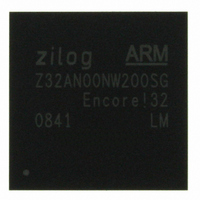
Z32AN00NW200SG Zilog, Z32AN00NW200SG Datasheet - Page 133

Z32AN00NW200SG
Manufacturer Part Number
Z32AN00NW200SG
Description
IC ARM922T MCU 200MHZ 256-BGA
Manufacturer
Zilog
Series
Encore!® 32r
Datasheet
1.Z32AN00NW200SG.pdf
(196 pages)
Specifications of Z32AN00NW200SG
Core Processor
ARM9
Core Size
16/32-Bit
Speed
200MHz
Connectivity
EBI/EMI, IrDA, SmartCard, SPI, UART/USART, USB OTG
Peripherals
DMA, LCD, Magnetic Card Reader, POR, PWM, WDT
Number Of I /o
76
Program Memory Type
ROMless
Ram Size
64K x 8
Voltage - Supply (vcc/vdd)
1.71 V ~ 3.6 V
Data Converters
A/D 4x10b
Oscillator Type
Internal
Operating Temperature
-40°C ~ 85°C
Package / Case
256-LBGA
For Use With
269-4713 - KIT DEV ENCORE 32 SERIES
Lead Free Status / RoHS Status
Lead free / RoHS Compliant
Eeprom Size
-
Program Memory Size
-
Other names
269-4717
Available stocks
Company
Part Number
Manufacturer
Quantity
Price
- Current page: 133 of 196
- Download datasheet (4Mb)
Z32AN Series Data Sheet
16.2.3 Reading the Timer Count Values
16.2.4 Timer Output Signal Operation
16.2.5 Registers (
16.2.5.1
16.2.5.2
DS0200-003
The current count value in the timers can be read while the timer is counting (TEN = “1”). This capability has
no effect on timer operation.
The timer output is toggled every time the counter is reloaded.
31:16
15:00
31:16
Offset 000h: T16_x – Timer
Offset 004h: T16_x_R – Timer Compare
Bits
Bits
Compare Mode: When the timer is disabled, the Timer Output signal is set to the value of
TPOL. When the timer is enabled, the Timer Output signal is complemented (changes state
from Low-to-High or High-to-Low) upon Compare.
Gated Mode:
o
o
Capture/Compare Mode:
o
o
Type
Type
RW
TPOL = “0”: Timer counts when the Timer Input signal is High (“1”) and interrupts are
generated on the falling edge of the Timer Input or upon Timer Reload.
TPOL = “1”: Timer counts when the Timer Input signal is Low (“0”) and interrupts are
generated on the rising edge of the Timer Input or upon Timer Reload.
TPOL = “0”: Counting begins after the first rising edge of the Timer Input signal. The
current count is captured on subsequent rising edges of the Timer Input signal.
TPOL = “1”: Counting begins after the first falling edge of the Timer Input signal. The
current count is captured on subsequent falling edges of the Timer Input signal.
Offset
RO
RO
000h
004h
008h
00Ch
010h
TMR0→FFFE3000h, TMR1→FFFE4000h, TMR2→FFFE5000h, TMR3→FFFE6000h
Reset
Reset
0001h
0
0
T16_x_PWM
T16_x_CTL
T16_x_INT
Description
Reserved
Count (COUNT): Stores the current 16-bit timer count value. Writing to this register
while the timer is enabled is not recommended. If this is written during counting, the
16-bit written value is placed in the counter at the next clock edge. The counter
continues counting from the new value.
Description
Reserved
Register
T16_x_R
T16_x
Description
Timer Register
Timer Compare Register
Timer PWM Register
Timer Interrupt Register
Timer Control Register
Page 120
)
Related parts for Z32AN00NW200SG
Image
Part Number
Description
Manufacturer
Datasheet
Request
R

Part Number:
Description:
Communication Controllers, ZILOG INTELLIGENT PERIPHERAL CONTROLLER (ZIP)
Manufacturer:
Zilog, Inc.
Datasheet:

Part Number:
Description:
KIT DEV FOR Z8 ENCORE 16K TO 64K
Manufacturer:
Zilog
Datasheet:

Part Number:
Description:
KIT DEV Z8 ENCORE XP 28-PIN
Manufacturer:
Zilog
Datasheet:

Part Number:
Description:
DEV KIT FOR Z8 ENCORE 8K/4K
Manufacturer:
Zilog
Datasheet:

Part Number:
Description:
KIT DEV Z8 ENCORE XP 28-PIN
Manufacturer:
Zilog
Datasheet:

Part Number:
Description:
DEV KIT FOR Z8 ENCORE 4K TO 8K
Manufacturer:
Zilog
Datasheet:

Part Number:
Description:
CMOS Z8 microcontroller. ROM 16 Kbytes, RAM 256 bytes, speed 16 MHz, 32 lines I/O, 3.0V to 5.5V
Manufacturer:
Zilog, Inc.
Datasheet:

Part Number:
Description:
Low-cost microcontroller. 512 bytes ROM, 61 bytes RAM, 8 MHz
Manufacturer:
Zilog, Inc.
Datasheet:

Part Number:
Description:
Z8 4K OTP Microcontroller
Manufacturer:
Zilog, Inc.
Datasheet:

Part Number:
Description:
CMOS SUPER8 ROMLESS MCU
Manufacturer:
Zilog, Inc.
Datasheet:

Part Number:
Description:
SL1866 CMOSZ8 OTP Microcontroller
Manufacturer:
Zilog, Inc.
Datasheet:

Part Number:
Description:
SL1866 CMOSZ8 OTP Microcontroller
Manufacturer:
Zilog, Inc.
Datasheet:

Part Number:
Description:
OTP (KB) = 1, RAM = 125, Speed = 12, I/O = 14, 8-bit Timers = 2, Comm Interfaces Other Features = Por, LV Protect, Voltage = 4.5-5.5V
Manufacturer:
Zilog, Inc.
Datasheet:

Part Number:
Description:
Manufacturer:
Zilog, Inc.
Datasheet:


