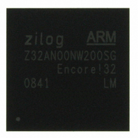
Z32AN00NW200SG Zilog, Z32AN00NW200SG Datasheet - Page 77

Z32AN00NW200SG
Manufacturer Part Number
Z32AN00NW200SG
Description
IC ARM922T MCU 200MHZ 256-BGA
Manufacturer
Zilog
Series
Encore!® 32r
Datasheet
1.Z32AN00NW200SG.pdf
(196 pages)
Specifications of Z32AN00NW200SG
Core Processor
ARM9
Core Size
16/32-Bit
Speed
200MHz
Connectivity
EBI/EMI, IrDA, SmartCard, SPI, UART/USART, USB OTG
Peripherals
DMA, LCD, Magnetic Card Reader, POR, PWM, WDT
Number Of I /o
76
Program Memory Type
ROMless
Ram Size
64K x 8
Voltage - Supply (vcc/vdd)
1.71 V ~ 3.6 V
Data Converters
A/D 4x10b
Oscillator Type
Internal
Operating Temperature
-40°C ~ 85°C
Package / Case
256-LBGA
For Use With
269-4713 - KIT DEV ENCORE 32 SERIES
Lead Free Status / RoHS Status
Lead free / RoHS Compliant
Eeprom Size
-
Program Memory Size
-
Other names
269-4717
Available stocks
Company
Part Number
Manufacturer
Quantity
Price
- Current page: 77 of 196
- Download datasheet (4Mb)
Z32AN Series Data Sheet
9.2.8.3
9.2.8.4
9.2.8.5
9.2.8.6
9.2.9
9.3
DS0200-003
when no card swipe is active. MCR_AUX_ADC allows the programmer to sample the ADC while the track is
still active. See section 9.2.7 for more details.
The reference voltage can be adjusted through the programmable gain amplifier for the voltage reference of
the ADC. Increasing the peak to peak input range is achieved by changing MCR_ADC.REFCAL to adjust
the ratio of input gain from 1 to 10. See section 9.2.7 for more details.
The threshold settings should be such that the noise of the MCR does not exceed the threshold limits.
The maximum delta time can be safely set at the maximum value (FFFh), though the lowest bit rate
(150bps) with the highest sample rate (266.7kHz) should imply that 7F2h should correspond to a “bit too
wide” condition.
Once the above parameters have been programmed the MCR channels can be enabled via
MCR_CTRL.IENn. Once this is done, delta time information is moved into the FIFO as a card is swiped and
the thresholds are crossed. A time-out interrupt will arrive when the swipe is completed. A channel may be
disabled at any time by clearing its MCR_CTRL.IENn. Enabling tracks affects the sample rate. See section
9.2.8.1 for more details.
The user can rely either upon FIFO and time-out interrupts or DMA to move data out of MCR_FIFO into a
memory buffer. If multiple tracks are enabled, the buffer will contain data from one track interleaved with
data from the other tracks, so it will be necessary to sort the data according to the track number stored with
the delta time information. When a time-out occurs, the peak detector for that channel continues to search
for another swipe and begins to move data into the FIFO as soon as more peaks begin to be detected.
Each track has an internal 12-bit timer. An interrupt can be generated on the time-out of each track, or a
single time-out can be generated on the time-out of the “last” track. This simplifies MCR interrupt handling.
A time-out is considered to be the “last” if the other two timers are either: 1) not enabled; 2) already timed-
out; or 3) have not encountered an initial peak (never started). The card time-out is enabled by setting
MCR_CTRL.CARD_TO_IEN.
Registers (Base → FFFF3000h)
Card Time-out and Track Timers
Programmable Gain Amplifier
Threshold Programming
Max Delta Time Programming
Enabling Channels and Handling FIFO Data
014h – 01Ch
020h – 028h
Offset
00Ch
02Ch
000h
004h
008h
010h
MCR_AUX_ADC
MCRn_THRS
MCRn_DCO
MCR_CTRL
MCR_FIFO
MCR_TMR
MCR_ADC
Register
MCR_INT
Description
MCR Global Control Register
MCR Interrupt Control and Status
MCR Timing Register
MCR FIFO Register
MCR ADC Register
MCR”N” DC Offset Register (N = 0, 1, or 2)
MCR”N” DC Threshold Register (N = 0, 1, or 2)
MCR Auxiliary ADC Register
Page 64
Related parts for Z32AN00NW200SG
Image
Part Number
Description
Manufacturer
Datasheet
Request
R

Part Number:
Description:
Communication Controllers, ZILOG INTELLIGENT PERIPHERAL CONTROLLER (ZIP)
Manufacturer:
Zilog, Inc.
Datasheet:

Part Number:
Description:
KIT DEV FOR Z8 ENCORE 16K TO 64K
Manufacturer:
Zilog
Datasheet:

Part Number:
Description:
KIT DEV Z8 ENCORE XP 28-PIN
Manufacturer:
Zilog
Datasheet:

Part Number:
Description:
DEV KIT FOR Z8 ENCORE 8K/4K
Manufacturer:
Zilog
Datasheet:

Part Number:
Description:
KIT DEV Z8 ENCORE XP 28-PIN
Manufacturer:
Zilog
Datasheet:

Part Number:
Description:
DEV KIT FOR Z8 ENCORE 4K TO 8K
Manufacturer:
Zilog
Datasheet:

Part Number:
Description:
CMOS Z8 microcontroller. ROM 16 Kbytes, RAM 256 bytes, speed 16 MHz, 32 lines I/O, 3.0V to 5.5V
Manufacturer:
Zilog, Inc.
Datasheet:

Part Number:
Description:
Low-cost microcontroller. 512 bytes ROM, 61 bytes RAM, 8 MHz
Manufacturer:
Zilog, Inc.
Datasheet:

Part Number:
Description:
Z8 4K OTP Microcontroller
Manufacturer:
Zilog, Inc.
Datasheet:

Part Number:
Description:
CMOS SUPER8 ROMLESS MCU
Manufacturer:
Zilog, Inc.
Datasheet:

Part Number:
Description:
SL1866 CMOSZ8 OTP Microcontroller
Manufacturer:
Zilog, Inc.
Datasheet:

Part Number:
Description:
SL1866 CMOSZ8 OTP Microcontroller
Manufacturer:
Zilog, Inc.
Datasheet:

Part Number:
Description:
OTP (KB) = 1, RAM = 125, Speed = 12, I/O = 14, 8-bit Timers = 2, Comm Interfaces Other Features = Por, LV Protect, Voltage = 4.5-5.5V
Manufacturer:
Zilog, Inc.
Datasheet:

Part Number:
Description:
Manufacturer:
Zilog, Inc.
Datasheet:


