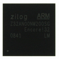
Z32AN00NW200SG Zilog, Z32AN00NW200SG Datasheet - Page 189

Z32AN00NW200SG
Manufacturer Part Number
Z32AN00NW200SG
Description
IC ARM922T MCU 200MHZ 256-BGA
Manufacturer
Zilog
Series
Encore!® 32r
Datasheet
1.Z32AN00NW200SG.pdf
(196 pages)
Specifications of Z32AN00NW200SG
Core Processor
ARM9
Core Size
16/32-Bit
Speed
200MHz
Connectivity
EBI/EMI, IrDA, SmartCard, SPI, UART/USART, USB OTG
Peripherals
DMA, LCD, Magnetic Card Reader, POR, PWM, WDT
Number Of I /o
76
Program Memory Type
ROMless
Ram Size
64K x 8
Voltage - Supply (vcc/vdd)
1.71 V ~ 3.6 V
Data Converters
A/D 4x10b
Oscillator Type
Internal
Operating Temperature
-40°C ~ 85°C
Package / Case
256-LBGA
For Use With
269-4713 - KIT DEV ENCORE 32 SERIES
Lead Free Status / RoHS Status
Lead free / RoHS Compliant
Eeprom Size
-
Program Memory Size
-
Other names
269-4717
Available stocks
Company
Part Number
Manufacturer
Quantity
Price
- Current page: 189 of 196
- Download datasheet (4Mb)
Z32AN Series Data Sheet
20.4 Using Output
20.5 Configuring Interrupts
20.6 Handling Interrupts
20.7 Wake Function
DS0200-003
A GPIO pin can always be used as an input. The state of the pin can be sampled through GPIO_IN even
when configured to operate as a primary function (GPIO_EN = ‘0’) or when configured as an output
(GPIO_OE = ‘1’).
To be used as an output, GPIO_EN must be set. Once set, the pin can be forced to drive a value on the pin
by setting GPIO_OE. With GPIO_OE=1, setting GPIO_OUT to 0 drive a ‘0’, while GPIO_OUT=1 drives a ‘1’.
The pin can be tri-stated by clearing GPIO_OE. GPIO_EN, GPIO_OE, and GPIO_OUT can be modified
either by writing to them directly or by writing to the associated SET and CLR registers. This allows bits to be
changed without a Read-Modify-Write operation.
Below is the suggested sequence for the initial configuration of GPIO interrupts. This can be done for any
number of GPIO bits. The GPIO Interrupt function can be used independent of the GPIO_EN and GPIO_OE
settings.
The recommended sequence of GPIO interrupt handling is provided below:
Below are suggested steps to enable wake. Like interrupts, wake is independent of GPIO_EN and
GPIO_OE:
1.
2.
3.
4.
5.
6.
7.
1.
2.
3.
4.
5.
1.
2.
3.
4.
Disable interrupts by clearing GPIO_IEN. This prevents the Interrupt Pending Flop from being
set but does not mask an already pending interrupt in the flop. See JK-flop labeled Interrupt
Pending Flop in Figure 20-1. GPIO_IEN can also be cleared by writing to GPIO_IEN_CLR.
Clear any pending interrupts by writing to GPIO_ICLR. This clears the Interrupt Pending Flop.
Write to GPIO_IMOD to select level/edge mode.
Write to GPIO_IPOL to select either rising/falling trigger level.
Write to GPIO_ISEL to select either A/B channel. This provides two priority levels within the
interrupt controller.
Write to GPIO_IEN to re-enable interrupts. Once set, the Interrupt Pending Flop can be set
and interrupts are active and ready. GPIO_IEN can also be set by writing to GPIO_IEN_SET.
Configure the Interrupt Controller as given section Chapter 6:. You may want to do this last
step prior to setting the GPIO_IEN bits.
Based upon GPIO_ISEL, read either GPIO_IAST or GPIO_IBST to determine the source(s).
Perform application specific interrupt tasks associated with the bit(s).
Clear the Interrupt Pending Flop by writing to GPIO_ICLR. This also clears and re-arms the
rising and falling edge trigger flops.
Signal and End-of-Interrupt to the interrupt controller. See section Chapter 6: for more details
Return from the ISR.
Set the polarity (rising or falling edge) by writing to GPIO_IPOL. The Wake function relies
upon rising and falling edge detectors to detect and latch the transition on the GPIO pin. These
flops operate asynchronously and do not require the GPIO clock to be active.
Clear the edge detector flops by writing to the GPIO_ICLR register.
Activate the GPIO Wake function by writing to the GPIO_WKEN or GPIO_WKEN_SET
register.
Configure the PMU to wake upon GPIO per section Chapter 3:.
Page 176
Related parts for Z32AN00NW200SG
Image
Part Number
Description
Manufacturer
Datasheet
Request
R

Part Number:
Description:
Communication Controllers, ZILOG INTELLIGENT PERIPHERAL CONTROLLER (ZIP)
Manufacturer:
Zilog, Inc.
Datasheet:

Part Number:
Description:
KIT DEV FOR Z8 ENCORE 16K TO 64K
Manufacturer:
Zilog
Datasheet:

Part Number:
Description:
KIT DEV Z8 ENCORE XP 28-PIN
Manufacturer:
Zilog
Datasheet:

Part Number:
Description:
DEV KIT FOR Z8 ENCORE 8K/4K
Manufacturer:
Zilog
Datasheet:

Part Number:
Description:
KIT DEV Z8 ENCORE XP 28-PIN
Manufacturer:
Zilog
Datasheet:

Part Number:
Description:
DEV KIT FOR Z8 ENCORE 4K TO 8K
Manufacturer:
Zilog
Datasheet:

Part Number:
Description:
CMOS Z8 microcontroller. ROM 16 Kbytes, RAM 256 bytes, speed 16 MHz, 32 lines I/O, 3.0V to 5.5V
Manufacturer:
Zilog, Inc.
Datasheet:

Part Number:
Description:
Low-cost microcontroller. 512 bytes ROM, 61 bytes RAM, 8 MHz
Manufacturer:
Zilog, Inc.
Datasheet:

Part Number:
Description:
Z8 4K OTP Microcontroller
Manufacturer:
Zilog, Inc.
Datasheet:

Part Number:
Description:
CMOS SUPER8 ROMLESS MCU
Manufacturer:
Zilog, Inc.
Datasheet:

Part Number:
Description:
SL1866 CMOSZ8 OTP Microcontroller
Manufacturer:
Zilog, Inc.
Datasheet:

Part Number:
Description:
SL1866 CMOSZ8 OTP Microcontroller
Manufacturer:
Zilog, Inc.
Datasheet:

Part Number:
Description:
OTP (KB) = 1, RAM = 125, Speed = 12, I/O = 14, 8-bit Timers = 2, Comm Interfaces Other Features = Por, LV Protect, Voltage = 4.5-5.5V
Manufacturer:
Zilog, Inc.
Datasheet:

Part Number:
Description:
Manufacturer:
Zilog, Inc.
Datasheet:


