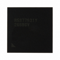
R5S77631Y266BGV Renesas Electronics America, R5S77631Y266BGV Datasheet - Page 756

R5S77631Y266BGV
Manufacturer Part Number
R5S77631Y266BGV
Description
IC SUPERH MPU ROMLESS 499BGA
Manufacturer
Renesas Electronics America
Series
SuperH® SH7780r
Datasheet
1.R5S77631Y266BGV.pdf
(2056 pages)
Specifications of R5S77631Y266BGV
Core Processor
SH-4A
Core Size
32-Bit
Speed
266MHz
Connectivity
Audio Codec, I²C, MMC, SCI, SIM, SIO, SSI, USB
Peripherals
DMA, LCD, POR, WDT
Number Of I /o
107
Program Memory Type
ROMless
Ram Size
16K x 8
Voltage - Supply (vcc/vdd)
1.15 V ~ 1.35 V
Data Converters
A/D 4x10b; D/A 2x8b
Oscillator Type
External
Operating Temperature
-20°C ~ 75°C
Package / Case
499-BGA
Lead Free Status / RoHS Status
Lead free / RoHS Compliant
Eeprom Size
-
Program Memory Size
-
Available stocks
Company
Part Number
Manufacturer
Quantity
Price
Company:
Part Number:
R5S77631Y266BGV
Manufacturer:
Renesas Electronics America
Quantity:
10 000
- Current page: 756 of 2056
- Download datasheet (10Mb)
Section 18 Power-Down Mode
18.8
18.8.1
When entering the RTC power supply backup mode with the VDD power supply (1.2 V) turned
off, the VDD power supply should be turned off while the XRTCSTBI signal is held low. By
turning off the VDD power supply, the currents that might be generated in the VDD (1.2 V)
operating region can be eliminated to reduce power consumption. If the clock has been supplied
from the 32.768-Hz crystal, the RTC continues counting of its second to year counters while the
VDD (1.2 V) power supply is turned off.
18.8.2
The RTC power supply backup mode is canceled by a power-on reset. Even when any interrupt
condition is satisfied in the RTC power supply backup mode, the interrupt-generating condition
will be canceled by the power-on reset. RTC power supply backup mode can be canceled in the
following steps.
1. Turn on the VDD power supply (1.2 V) while holding the PRESET signal low.
2. Since the VDD-RTC (3.3 V), which is exclusively used for the RTC, is supplied, drive the
3. Hold the PRESET signal low until the RTC is reset by the power-on reset, and then cancel the
Table 18.5 shows the configuration of the pins related to RTC power supply backup mode.
Table 18.5 Pin Configuration
Rev. 2.00 May 22, 2009 Page 686 of 1982
REJ09B0256-0200
Pin Name
XRTCSTBI
XRTCSTBI signal high only after the power-on oscillation stabilization time has elapsed after
the VDD (1.2 V) becomes stable. This is to prevent the LSI from being damaged by the
transient current.
power-on reset.
RTC Power Supply Backup
Transition to RTC Power Supply Backup Mode
Canceling RTC Power Supply Backup Mode
Function
RTC standby
I/O
Input
Description
When this pin goes low, the LSI enters RTC
power supply backup mode.
Related parts for R5S77631Y266BGV
Image
Part Number
Description
Manufacturer
Datasheet
Request
R

Part Number:
Description:
KIT STARTER FOR M16C/29
Manufacturer:
Renesas Electronics America
Datasheet:

Part Number:
Description:
KIT STARTER FOR R8C/2D
Manufacturer:
Renesas Electronics America
Datasheet:

Part Number:
Description:
R0K33062P STARTER KIT
Manufacturer:
Renesas Electronics America
Datasheet:

Part Number:
Description:
KIT STARTER FOR R8C/23 E8A
Manufacturer:
Renesas Electronics America
Datasheet:

Part Number:
Description:
KIT STARTER FOR R8C/25
Manufacturer:
Renesas Electronics America
Datasheet:

Part Number:
Description:
KIT STARTER H8S2456 SHARPE DSPLY
Manufacturer:
Renesas Electronics America
Datasheet:

Part Number:
Description:
KIT STARTER FOR R8C38C
Manufacturer:
Renesas Electronics America
Datasheet:

Part Number:
Description:
KIT STARTER FOR R8C35C
Manufacturer:
Renesas Electronics America
Datasheet:

Part Number:
Description:
KIT STARTER FOR R8CL3AC+LCD APPS
Manufacturer:
Renesas Electronics America
Datasheet:

Part Number:
Description:
KIT STARTER FOR RX610
Manufacturer:
Renesas Electronics America
Datasheet:

Part Number:
Description:
KIT STARTER FOR R32C/118
Manufacturer:
Renesas Electronics America
Datasheet:

Part Number:
Description:
KIT DEV RSK-R8C/26-29
Manufacturer:
Renesas Electronics America
Datasheet:

Part Number:
Description:
KIT STARTER FOR SH7124
Manufacturer:
Renesas Electronics America
Datasheet:

Part Number:
Description:
KIT STARTER FOR H8SX/1622
Manufacturer:
Renesas Electronics America
Datasheet:

Part Number:
Description:
KIT DEV FOR SH7203
Manufacturer:
Renesas Electronics America
Datasheet:


