NNDK-MOD5272-KIT NetBurner Inc, NNDK-MOD5272-KIT Datasheet - Page 522
NNDK-MOD5272-KIT
Manufacturer Part Number
NNDK-MOD5272-KIT
Description
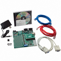
KIT DEVELOP NETWORK FOR MOD5272
Manufacturer
NetBurner Inc
Series
ColdFire®r
Datasheets
1.MOD5272-100IR.pdf
(2 pages)
2.MOD5272-100IR.pdf
(550 pages)
3.NNDK-MOD5282-KIT.pdf
(2 pages)
Specifications of NNDK-MOD5272-KIT
Main Purpose
*
Embedded
*
Utilized Ic / Part
MOD5272
Primary Attributes
*
Secondary Attributes
*
Processor To Be Evaluated
MOD5272
Interface Type
RS-232, RS-485, USB
Lead Free Status / RoHS Status
Contains lead / RoHS non-compliant
Lead Free Status / RoHS Status
Lead free / RoHS Compliant, Contains lead / RoHS non-compliant
Other names
528-1001


PWM Electrical Specifications
The values in Table 23-24 correspond to Figure 23-24.
23.14 PWM Electrical Specifications
Table 23-25 lists PWM timings.
1
1
2
23-28
PW1
PW2
Name
Name
QSPI_CS[3:0]
T is defined as clock period in nS. See Table 23-6.
All timing references to SDCLK are given to its rising edge when bit 3 of the SDRAM control register is 0.
Parameter tested
QS1
QS2
QS3
QS4
QS5
QSPI_DOUT
QSPI_CLK
QSPI_DIN
2
2
QSPI_CS[3:0] to QSPI_CLK
QSPI_CLK high to QSPI_DOUT valid.
QSPI_CLK high to QSPI_DOUT invalid. (Output hold)
QSPI_DIN to QSPI_CLK (Input setup)
QSPI_DIN to QSPI_CLK (Input hold)
SDLCK high to PWM_OUT[2:0] valid, high or low.
SDLCK high to PWM_OUT[2:0] invalid. (Output hold)
QS1
Table 23-25. PWM Modules AC Timing Specifications
Table 23-24. QSPI Modules AC Timing Specifications
QS3
Figure 23-24. QSPI Timing
Characteristic
Characteristic
QS2
MCF5272 User’s Manual
1
QS4
Min
Min
1T
2.5
10
10
—
—
0
0–66 MHz
0–66 MHz
1
QS5
127T
Max
Max
20
11
—
—
—
—
MOTOROLA
1
Unit
Unit
nS
nS
nS
nS
nS
nS
nS
Related parts for NNDK-MOD5272-KIT
Image
Part Number
Description
Manufacturer
Datasheet
Request
R

Part Number:
Description:
BOARD SERIAL-ETHERNET 512K FLASH
Manufacturer:
NetBurner Inc
Datasheet:

Part Number:
Description:
PROCESSOR MODULE FLASH MOD5272
Manufacturer:
NetBurner Inc
Datasheet:

Part Number:
Description:
PROCESSOR MODULE 512KB FLASH
Manufacturer:
NetBurner Inc
Datasheet:

Part Number:
Description:
DUAL PORT SERIAL-ETHERNET
Manufacturer:
NetBurner Inc
Datasheet:

Part Number:
Description:
PROCESSOR MODULE FLASH
Manufacturer:
NetBurner Inc
Datasheet:

Part Number:
Description:
PROCESSOR MODULE 512KB FLASH
Manufacturer:
NetBurner Inc
Datasheet:

Part Number:
Description:
MOD5234 10/100 ETHERNET MODULE
Manufacturer:
NetBurner Inc
Datasheet:

Part Number:
Description:
KIT DEVELOP NETWORK FOR MOD5282
Manufacturer:
NetBurner Inc
Datasheet:

Part Number:
Description:
DUAL PORT SERIAL-ETHERNET
Manufacturer:
NetBurner Inc
Datasheet:

Part Number:
Description:
Ethernet Modules & Development Tools 32 Bit 66MHz 40 Pin DIP Industrial Temp
Manufacturer:
NetBurner Inc
Datasheet:

Part Number:
Description:
Ethernet Modules & Development Tools MOD5213 DEVELOPMENT KIT
Manufacturer:
NetBurner Inc

Part Number:
Description:
Ethernet Modules & Development Tools DUAL PORT SERIAL EHTERNET DEVICE
Manufacturer:
NetBurner Inc
Datasheet:

Part Number:
Description:
Ethernet ICs 32bit 147MHz CAN-to- Ethnt Device IndTemp
Manufacturer:
NetBurner Inc
Datasheet: