NNDK-MOD5272-KIT NetBurner Inc, NNDK-MOD5272-KIT Datasheet - Page 190
NNDK-MOD5272-KIT
Manufacturer Part Number
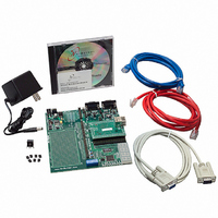
NNDK-MOD5272-KIT
Description
KIT DEVELOP NETWORK FOR MOD5272
Manufacturer
NetBurner Inc
Series
ColdFire®r
Datasheets
1.MOD5272-100IR.pdf
(2 pages)
2.MOD5272-100IR.pdf
(550 pages)
3.NNDK-MOD5282-KIT.pdf
(2 pages)
Specifications of NNDK-MOD5272-KIT
Main Purpose
*
Embedded
*
Utilized Ic / Part
MOD5272
Primary Attributes
*
Secondary Attributes
*
Processor To Be Evaluated
MOD5272
Interface Type
RS-232, RS-485, USB
Lead Free Status / RoHS Status
Contains lead / RoHS non-compliant
Lead Free Status / RoHS Status
Lead free / RoHS Compliant, Contains lead / RoHS non-compliant
Other names
528-1001


Chip Select Registers
8.1.3 Boot CS0 Operation
CS0 is enabled after reset and is used to access boot ROM. The memory port width of CS0
is defined by the state of QSPI_CLK/BUSW1 and QSPI_CS0/BUSW0. These two bits
should be configured to define the width of the boot ROM connected to CS0, as described
in Section 19.18, “Operating Mode Configuration Pins.”
8.2 Chip Select Registers
Each chip select is controlled through two 32-bit registers. The chip select base registers
(CSBR0–CSBR7) are used to enable the chip select and to configure the base address, port
size, bus interface type, and address space. The chip select option registers
(CSOR0–CSOR7) are used to configure the address mask, additional setup/hold, extended
burst capability, wait states, and read/write access.
8-2
A detailed description of each bus access type supported by the
MCF5272 device is given in Chapter 20, “w Bus Operation.”
1
+ 0x04C CSOR1 CS option register 1
+ 0x05C CSOR3 CS option register 3
+ 0x06C CSOR5 CS option register 5
+ 0x07C CSOR7 CS option register 7
+ 0x040
+ 0x044 CSOR0 CS option register 0
+ 0x048
+ 0x050
+ 0x054 CSOR2 CS option register 2
+ 0x058
+ 0x060
+ 0x064 CSOR4 CS option register 4
+ 0x068
+ 0x070
+ 0x074 CSOR6 CS option register 6
+ 0x078
Offset
The nibble shown as x resets as 00xx, where the undefined bits represent
the BW field. QSPI_CS0/BUSW0 and QSPI_CLK/BUSW1 program the
bus width for CS0 at reset
Table 8-1. CSCR and CSOR Values after Reset
CSBR0 CS base register 0
CSBR1 CS base register 1
CSBR2 CS base register 2
CSBR3 CS base register 3
CSBR4 CS base register 4
CSBR5 CS base register 5
CSBR6 CS base register 6
CSBR7 CS base register 7
Name
MCF5272 User’s Manual
Chip Select Register
NOTE:
0x0000_0x01
0xFFFF_F078
0xFFFF_F078
0xFFFF_F078
0xFFFF_F078
0xFFFF_F078
0xFFFF_F078
0xFFFF_F078
0xFFFF_F078
0x0000_1300
0x0000_2300
0x0000_3300
0x0000_4300
0x0000_5300
0x0000_6300
0x0000_7700
Reset
1
MOTOROLA
Related parts for NNDK-MOD5272-KIT
Image
Part Number
Description
Manufacturer
Datasheet
Request
R

Part Number:
Description:
BOARD SERIAL-ETHERNET 512K FLASH
Manufacturer:
NetBurner Inc
Datasheet:

Part Number:
Description:
PROCESSOR MODULE FLASH MOD5272
Manufacturer:
NetBurner Inc
Datasheet:

Part Number:
Description:
PROCESSOR MODULE 512KB FLASH
Manufacturer:
NetBurner Inc
Datasheet:

Part Number:
Description:
DUAL PORT SERIAL-ETHERNET
Manufacturer:
NetBurner Inc
Datasheet:

Part Number:
Description:
PROCESSOR MODULE FLASH
Manufacturer:
NetBurner Inc
Datasheet:

Part Number:
Description:
PROCESSOR MODULE 512KB FLASH
Manufacturer:
NetBurner Inc
Datasheet:

Part Number:
Description:
MOD5234 10/100 ETHERNET MODULE
Manufacturer:
NetBurner Inc
Datasheet:

Part Number:
Description:
KIT DEVELOP NETWORK FOR MOD5282
Manufacturer:
NetBurner Inc
Datasheet:

Part Number:
Description:
DUAL PORT SERIAL-ETHERNET
Manufacturer:
NetBurner Inc
Datasheet:

Part Number:
Description:
Ethernet Modules & Development Tools 32 Bit 66MHz 40 Pin DIP Industrial Temp
Manufacturer:
NetBurner Inc
Datasheet:

Part Number:
Description:
Ethernet Modules & Development Tools MOD5213 DEVELOPMENT KIT
Manufacturer:
NetBurner Inc

Part Number:
Description:
Ethernet Modules & Development Tools DUAL PORT SERIAL EHTERNET DEVICE
Manufacturer:
NetBurner Inc
Datasheet:

Part Number:
Description:
Ethernet ICs 32bit 147MHz CAN-to- Ethnt Device IndTemp
Manufacturer:
NetBurner Inc
Datasheet: