NNDK-MOD5272-KIT NetBurner Inc, NNDK-MOD5272-KIT Datasheet - Page 227
NNDK-MOD5272-KIT
Manufacturer Part Number
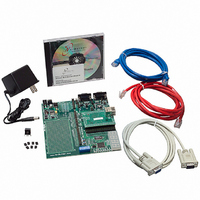
NNDK-MOD5272-KIT
Description
KIT DEVELOP NETWORK FOR MOD5272
Manufacturer
NetBurner Inc
Series
ColdFire®r
Datasheets
1.MOD5272-100IR.pdf
(2 pages)
2.MOD5272-100IR.pdf
(550 pages)
3.NNDK-MOD5282-KIT.pdf
(2 pages)
Specifications of NNDK-MOD5272-KIT
Main Purpose
*
Embedded
*
Utilized Ic / Part
MOD5272
Primary Attributes
*
Secondary Attributes
*
Processor To Be Evaluated
MOD5272
Interface Type
RS-232, RS-485, USB
Lead Free Status / RoHS Status
Contains lead / RoHS non-compliant
Lead Free Status / RoHS Status
Lead free / RoHS Compliant, Contains lead / RoHS non-compliant
Other names
528-1001


MOTOROLA
The descriptor controller opens and closes the buffer descriptors. The DMA controller
manages the data transfer. As soon as the DMA channel is initialized, it begins transferring
data. An on-board RAM acts as both a transmit and receive FIFO, and also provides scratch
memory for the FEC.
The RAM is the focal point of all data flow in the FEC. The RAM is divided into three
sections: transmit FIFO, receive FIFO, and descriptor controller memory. User data flows
to or from the DMA unit from or to the receive/transmit FIFOs. Transmit data flows from
the transmit FIFO into the transmit block. Receive data flows from the receive block into
the receive FIFO.
The user controls the FEC by writing into control registers located in each block. The
control and status registers (CSRs) provide global control (for example, Ethernet reset and
enable) and interrupt handling. The MII block provides a serial channel for the FEC and
external physical layer device to pass control and status information.
The descriptor controller manages data flow in both transmit and receive directions. It is
programmed with microcode to open and close buffer descriptors, control the transmit
collision recovery process, and filter received frame addresses.
The descriptor controller accesses both the transmit and receive descriptor rings through the
descriptor access block. The descriptor access block acts as a dedicated single channel
DMA that either reads a descriptor in external user memory or writes an updated descriptor
back into user memory.
11.3 Transceiver Connection
The FEC supports both an MII interface for 10/100 Mbps Ethernet and a seven-wire serial
interface for 10 Mbps Ethernet. The interface mode is selected by RCR[MII_MODE]. In
MII mode, the 802.3 standard defines and the FEC module supports 18 signals. These are
shown in Table 11-1.
Transmit clock
Transmit enable
Transmit data
Transmit error
Collision
Carrier sense
Receive clock
Receive enable
Receive data
Receive error
Signal Description
Chapter 11. Ethernet Module
Table 11-1. MII Mode
MCF5272 Pin
E_TxD[3:0]
E_RxD[3:0]
E_RxCLK
E_TxCLK
E_RxER
E_TxEN
E_TxER
E_RxDV
E_CRS
E_COL
Transceiver Connection
11-3
Related parts for NNDK-MOD5272-KIT
Image
Part Number
Description
Manufacturer
Datasheet
Request
R

Part Number:
Description:
BOARD SERIAL-ETHERNET 512K FLASH
Manufacturer:
NetBurner Inc
Datasheet:

Part Number:
Description:
PROCESSOR MODULE FLASH MOD5272
Manufacturer:
NetBurner Inc
Datasheet:

Part Number:
Description:
PROCESSOR MODULE 512KB FLASH
Manufacturer:
NetBurner Inc
Datasheet:

Part Number:
Description:
DUAL PORT SERIAL-ETHERNET
Manufacturer:
NetBurner Inc
Datasheet:

Part Number:
Description:
PROCESSOR MODULE FLASH
Manufacturer:
NetBurner Inc
Datasheet:

Part Number:
Description:
PROCESSOR MODULE 512KB FLASH
Manufacturer:
NetBurner Inc
Datasheet:

Part Number:
Description:
MOD5234 10/100 ETHERNET MODULE
Manufacturer:
NetBurner Inc
Datasheet:

Part Number:
Description:
KIT DEVELOP NETWORK FOR MOD5282
Manufacturer:
NetBurner Inc
Datasheet:

Part Number:
Description:
DUAL PORT SERIAL-ETHERNET
Manufacturer:
NetBurner Inc
Datasheet:

Part Number:
Description:
Ethernet Modules & Development Tools 32 Bit 66MHz 40 Pin DIP Industrial Temp
Manufacturer:
NetBurner Inc
Datasheet:

Part Number:
Description:
Ethernet Modules & Development Tools MOD5213 DEVELOPMENT KIT
Manufacturer:
NetBurner Inc

Part Number:
Description:
Ethernet Modules & Development Tools DUAL PORT SERIAL EHTERNET DEVICE
Manufacturer:
NetBurner Inc
Datasheet:

Part Number:
Description:
Ethernet ICs 32bit 147MHz CAN-to- Ethnt Device IndTemp
Manufacturer:
NetBurner Inc
Datasheet: