NNDK-MOD5272-KIT NetBurner Inc, NNDK-MOD5272-KIT Datasheet - Page 456
NNDK-MOD5272-KIT
Manufacturer Part Number
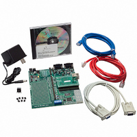
NNDK-MOD5272-KIT
Description
KIT DEVELOP NETWORK FOR MOD5272
Manufacturer
NetBurner Inc
Series
ColdFire®r
Datasheets
1.MOD5272-100IR.pdf
(2 pages)
2.MOD5272-100IR.pdf
(550 pages)
3.NNDK-MOD5282-KIT.pdf
(2 pages)
Specifications of NNDK-MOD5272-KIT
Main Purpose
*
Embedded
*
Utilized Ic / Part
MOD5272
Primary Attributes
*
Secondary Attributes
*
Processor To Be Evaluated
MOD5272
Interface Type
RS-232, RS-485, USB
Lead Free Status / RoHS Status
Contains lead / RoHS non-compliant
Lead Free Status / RoHS Status
Lead free / RoHS Compliant, Contains lead / RoHS non-compliant
Other names
528-1001


Bus and Control Signals
20.2.1 Address Bus (A[22:0])
These output signals provide the location of a bus transfer. The address can be external
SRAM, ROM, FLASH, SDRAM, or peripherals.
20.2.2 Data Bus (D[31:0])
These three-state bidirectional signals provide the general-purpose data path between the
MCF5272 and all other devices. The data bus can transfer 8, 16, 32, or 128 bits of data per
bus transfer. The MCF5272 can be configured for an external physical data bus of 32- or
16-bits width. When configured for 16-bit external data bus width, D[15:0] become GPIO
port C. A write cycle drives all 32 or 16 bits of the data bus regardless of the chip select port
width and operand size.
20.2.3 Read/Write (R/W)
This output signal defines the data transfer direction for the current bus cycle. A high (logic
one) level indicates a read cycle; a low (logic zero) level indicates a write cycle. During
SDRAM bus cycles R/W is driven high. When the CPU is in SLEEP or STOP modes, this
signal is driven high.
20-2
The ColdFire core outputs 32 bits of address to the internal bus
controller. Of these 32 bits, only A[22:0] are output to pins on
the MCF5272.
Use the OE signal to control any external data bus transceivers.
In systems containing numerous external peripherals, the chip
selects should be used to qualify any external transceivers. This
ensures the transceivers are active only when the desired
peripheral is accessed. Using only the R/W signal to control an
external transceiver may lead to data bus conflicts in some
system architectures.
Table 20-1. ColdFire Bus Signal Summary (Continued)
Signal Name
INT[6:1]
R/W
TEA
OE
TA
MCF5272 User’s Manual
Interrupt request
Output enable
Read/write
Transfer acknowledge
Transfer error acknowledge
NOTE:
NOTE:
Description
I/O
O
O
I
I
I
MOTOROLA
Related parts for NNDK-MOD5272-KIT
Image
Part Number
Description
Manufacturer
Datasheet
Request
R

Part Number:
Description:
BOARD SERIAL-ETHERNET 512K FLASH
Manufacturer:
NetBurner Inc
Datasheet:

Part Number:
Description:
PROCESSOR MODULE FLASH MOD5272
Manufacturer:
NetBurner Inc
Datasheet:

Part Number:
Description:
PROCESSOR MODULE 512KB FLASH
Manufacturer:
NetBurner Inc
Datasheet:

Part Number:
Description:
DUAL PORT SERIAL-ETHERNET
Manufacturer:
NetBurner Inc
Datasheet:

Part Number:
Description:
PROCESSOR MODULE FLASH
Manufacturer:
NetBurner Inc
Datasheet:

Part Number:
Description:
PROCESSOR MODULE 512KB FLASH
Manufacturer:
NetBurner Inc
Datasheet:

Part Number:
Description:
MOD5234 10/100 ETHERNET MODULE
Manufacturer:
NetBurner Inc
Datasheet:

Part Number:
Description:
KIT DEVELOP NETWORK FOR MOD5282
Manufacturer:
NetBurner Inc
Datasheet:

Part Number:
Description:
DUAL PORT SERIAL-ETHERNET
Manufacturer:
NetBurner Inc
Datasheet:

Part Number:
Description:
Ethernet Modules & Development Tools 32 Bit 66MHz 40 Pin DIP Industrial Temp
Manufacturer:
NetBurner Inc
Datasheet:

Part Number:
Description:
Ethernet Modules & Development Tools MOD5213 DEVELOPMENT KIT
Manufacturer:
NetBurner Inc

Part Number:
Description:
Ethernet Modules & Development Tools DUAL PORT SERIAL EHTERNET DEVICE
Manufacturer:
NetBurner Inc
Datasheet:

Part Number:
Description:
Ethernet ICs 32bit 147MHz CAN-to- Ethnt Device IndTemp
Manufacturer:
NetBurner Inc
Datasheet: