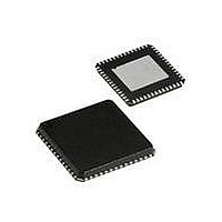
CYRF69213-40LFXC Cypress Semiconductor Corp, CYRF69213-40LFXC Datasheet - Page 30

CYRF69213-40LFXC
Manufacturer Part Number
CYRF69213-40LFXC
Description
IC PROC 8K FLASH 40VQFN
Manufacturer
Cypress Semiconductor Corp
Series
CYRFr
Type
Transceiverr
Datasheet
1.CYRF69213-40LFXC.pdf
(77 pages)
Specifications of CYRF69213-40LFXC
Package / Case
40-VQFN Exposed Pad, 40-HVQFN, 40-SQFN, 40-DHVQFN
Frequency
2.4GHz
Data Rate - Maximum
1Mbps
Modulation Or Protocol
ISM
Applications
General Purpose
Power - Output
4dBm
Sensitivity
-97dBm
Voltage - Supply
4 V ~ 5.5 V
Current - Receiving
23.4mA
Current - Transmitting
36.6mA
Data Interface
PCB, Surface Mount
Memory Size
8kB Flash, 256B SRAM
Antenna Connector
PCB, Surface Mount
Operating Temperature
0°C ~ 70°C
Operating Frequency
2497 MHz
Operating Supply Voltage
2.5 V or 3.3 V
Maximum Operating Temperature
+ 70 C
Minimum Operating Temperature
0 C
Mounting Style
SMD/SMT
Operating Temperature (min)
0C
Operating Temperature (max)
70C
Operating Temperature Classification
Commercial
Operating Supply Voltage (min)
1.8V
Operating Supply Voltage (typ)
2.5/3.3V
Operating Supply Voltage (max)
3.6V
Lead Free Status / RoHS Status
Lead free / RoHS Compliant
For Use With
770-1001 - ISP 4PORT CYPRESS ENCORE II MCU
Lead Free Status / Rohs Status
Lead free / RoHS Compliant
Other names
428-1934
Available stocks
Company
Part Number
Manufacturer
Quantity
Price
Part Number:
CYRF69213-40LFXC
Manufacturer:
CYPRESS/赛普拉斯
Quantity:
20 000
Table 40. Clock I/O Config (CLKIOCR) [0x32] [R/W]
CPU Clock During Sleep Mode
When the CPU enters sleep mode the CPUCLK Select (Bit [0],
Table
stopped. When the CPU comes out of sleep mode it is running
on the internal oscillator. The internal oscillator recovery time is
three clock cycles of the Internal 32 kHz Low power Oscillator.
If the system requires the CPU to run off the external clock after
awakening from sleep mode, firmware needs to switch the clock
source for the CPU.
Document #: 001-07552 Rev. *D
Bit #
Field
Read/Write
Default
Bits 7:2
Bits 1:0
36) is forced to the internal oscillator, and the oscillator is
Reserved
CLKOUT Select
0 0 = Internal 24 MHz Oscillator
0 1 = External crystal oscillator – external crystal oscillator on CLKIN and CLKOUT if the external crystal oscillator is
enabled, CLKIN input if the external oscillator is disabled
1 0 = Internal 32 kHz Low power Oscillator.However this configuration is not used in sleep mode.
1 1 = CPUCLK
7
–
0
Captimer Clock
6
–
0
Figure 11. Timer Capture Block Diagram
timer
1ms
16-bit counter
5
–
0
Reserved
Overflow
Interrupt
System Clock
4
0
-
Reset
The microcontroller supports two types of resets: Power on
Reset (POR) and Watchdog Reset (WDR). When reset is
initiated, all registers are restored to their default states and all
interrupts are disabled.
The occurrence of a reset is recorded in the System Status and
Control Register (CPU_SCR). Bits within this register record the
occurrence of POR and WDR Reset respectively. The firmware
can interrogate these bits to determine the cause of a reset.
The microcontroller resumes execution from Flash address
0x0000 after a reset. The internal clocking mode is active after a
reset, until changed by user firmware.
Note The CPU clock defaults to 3 MHz (Internal 24 MHz Oscil-
lator divide-by-8 mode) at POR to guarantee operation at the low
V
CC
Capture0 Int
that might be present during the supply ramp.
Configuration Status
Interrupt Controller
Capture Registers
Prescale Mux
and Control
3
0
-
Capture1 Int
2
0
-
R/W
CLKOUT Select
1
0
CYRF69213
Page 30 of 77
R/W
0
0
[+] Feedback


