CYRF69213-40LFXC Cypress Semiconductor Corp, CYRF69213-40LFXC Datasheet - Page 10
CYRF69213-40LFXC
Manufacturer Part Number
CYRF69213-40LFXC
Description
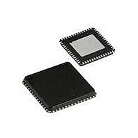
IC PROC 8K FLASH 40VQFN
Manufacturer
Cypress Semiconductor Corp
Series
CYRFr
Type
Transceiverr
Datasheet
1.CYRF69213-40LFXC.pdf
(77 pages)
Specifications of CYRF69213-40LFXC
Package / Case
40-VQFN Exposed Pad, 40-HVQFN, 40-SQFN, 40-DHVQFN
Frequency
2.4GHz
Data Rate - Maximum
1Mbps
Modulation Or Protocol
ISM
Applications
General Purpose
Power - Output
4dBm
Sensitivity
-97dBm
Voltage - Supply
4 V ~ 5.5 V
Current - Receiving
23.4mA
Current - Transmitting
36.6mA
Data Interface
PCB, Surface Mount
Memory Size
8kB Flash, 256B SRAM
Antenna Connector
PCB, Surface Mount
Operating Temperature
0°C ~ 70°C
Operating Frequency
2497 MHz
Operating Supply Voltage
2.5 V or 3.3 V
Maximum Operating Temperature
+ 70 C
Minimum Operating Temperature
0 C
Mounting Style
SMD/SMT
Operating Temperature (min)
0C
Operating Temperature (max)
70C
Operating Temperature Classification
Commercial
Operating Supply Voltage (min)
1.8V
Operating Supply Voltage (typ)
2.5/3.3V
Operating Supply Voltage (max)
3.6V
Lead Free Status / RoHS Status
Lead free / RoHS Compliant
For Use With
770-1001 - ISP 4PORT CYPRESS ENCORE II MCU
Lead Free Status / Rohs Status
Lead free / RoHS Compliant
Other names
428-1934
Available stocks
Company
Part Number
Manufacturer
Quantity
Price

Part Number:
CYRF69213-40LFXC
Manufacturer:
CYPRESS/赛普拉斯
Quantity:
20 000


SPI Connects to External Devices
The three SPI wires, MOSI, SCK, and SS are also drawn out of
the package as external pins to allow the user to interface their
own external devices (such as optical sensors and others)
CPU Architecture
This family of microcontrollers is based on a high performance,
8-bit, Harvard-architecture microprocessor. Five registers
control the primary operation of the CPU core. These registers
are affected by various instructions, but are not directly acces-
sible through the register space by the user.
Table 4. CPU Registers and Register Names
The 16-bit Program Counter Register (CPU_PC) allows for direct
addressing of the full eight Kbytes of program memory space.
Document #: 001-07552 Rev. *D
Flags
Program Counter
Accumulator
Stack Pointer
Index
Bit#
Bit Name
Register
7
DIR
6
INC
CPU_F
CPU_PC
CPU_A
CPU_SP
CPU_X
[5:0]
Address
Register Name
Byte 1
Figure 6. SPI Transaction Format
through SPI. The radio function also has its own SPI wires MISO
and IRQ, which can be used to send data back to the MCU
function or send an interrupt request to the MCU function. They
can also be configured as GPIO pins.
The Accumulator Register (CPU_A) is the general purpose
register that holds the results of instructions that specify any of
the source addressing modes.
The Index Register (CPU_X) holds an offset value that is used
in the indexed addressing modes. Typically, this is used to
address a block of data within the data memory space.
The Stack Pointer Register (CPU_SP) holds the address of the
current top-of-stack in the data memory space. It is affected by
the PUSH, POP, LCALL, CALL, RETI, and RET instructions,
which manage the software stack. It can also be affected by the
SWAP and ADD instructions.
The Flag Register (CPU_F) has three status bits: Zero Flag bit
[1]; Carry Flag bit [2]; Supervisory State bit [3]. The Global
Interrupt Enable bit [0] is used to globally enable or disable inter-
rupts. The user cannot manipulate the Supervisory State status
bit [3]. The flags are affected by arithmetic, logic, and shift opera-
tions. The manner in which each flag is changed is dependent
upon the instruction being executed (for example, AND, OR,
XOR). See
[7:0]
Data
Table
21.
Byte 1+N
CYRF69213
Page 10 of 77
[+] Feedback
Related parts for CYRF69213-40LFXC
Image
Part Number
Description
Manufacturer
Datasheet
Request
R

Part Number:
Description:
Manufacturer:
Cypress Semiconductor Corp
Datasheet:
Part Number:
Description:
Manufacturer:
Cypress Semiconductor Corp
Datasheet:
Part Number:
Description:
Manufacturer:
Cypress Semiconductor Corp
Datasheet:
Part Number:
Description:
Manufacturer:
Cypress Semiconductor Corp
Datasheet:
Part Number:
Description:
Manufacturer:
Cypress Semiconductor Corp
Datasheet: