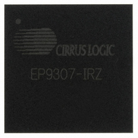
EP9307-IRZ Cirrus Logic Inc, EP9307-IRZ Datasheet - Page 18

EP9307-IRZ
Manufacturer Part Number
EP9307-IRZ
Description
IC ARM9 SOC ARM920T 272TFBGA
Manufacturer
Cirrus Logic Inc
Series
EP9r
Datasheets
1.EP9307-CRZ.pdf
(16 pages)
2.EP9307-CRZ.pdf
(50 pages)
3.EP9307-CRZ.pdf
(824 pages)
4.EP9307-CRZ.pdf
(48 pages)
Specifications of EP9307-IRZ
Core Size
16/32-Bit
Core Processor
ARM9
Speed
200MHz
Connectivity
EBI/EMI, Ethernet, I²C, IrDA, Keypad/Touchscreen, SPI, UART/USART, USB
Peripherals
AC'97, DMA, I²:S, LCD, LED, MaverickKey, POR, PWM, WDT
Number Of I /o
14
Program Memory Type
ROMless
Ram Size
32K x 8
Voltage - Supply (vcc/vdd)
1.65 V ~ 3.6 V
Data Converters
A/D 8x12b
Oscillator Type
External
Operating Temperature
-40°C ~ 85°C
Package / Case
272-TFBGA
Controller Family/series
(ARM9)
No. Of I/o's
14
Ram Memory Size
32MB
Cpu Speed
200MHz
No. Of Timers
3
No. Of Pwm Channels
1
Digital Ic Case Style
TFBGA
Embedded Interface Type
AC97, I2S, SPI, UART, USB
Rohs Compliant
Yes
Processor Series
EP93xx
Core
ARM920T
Data Bus Width
32 bit
3rd Party Development Tools
MDK-ARM, RL-ARM, ULINK2
Development Tools By Supplier
EDB9307A-Z
Lead Free Status / RoHS Status
Lead free / RoHS Compliant
For Use With
598-1133 - KIT DEVELOPMENT EP9307 ARM9
Eeprom Size
-
Program Memory Size
-
Lead Free Status / Rohs Status
Details
Other names
598-1256
Available stocks
Company
Part Number
Manufacturer
Quantity
Price
Company:
Part Number:
EP9307-IRZ
Manufacturer:
CIRRUS
Quantity:
3 468
Company:
Part Number:
EP9307-IRZR
Manufacturer:
Cirrus Logic Inc
Quantity:
10 000
- EP9307-CRZ PDF datasheet
- EP9307-CRZ PDF datasheet #2
- EP9307-CRZ PDF datasheet #3
- EP9307-CRZ PDF datasheet #4
- Current page: 18 of 824
- Download datasheet (13Mb)
EP93xx User’s Guide
xviii
Table 3-6. LDC/STC Opcode Map ..............................................................................................................3-16
Table 3-7. CDP Opcode Map ......................................................................................................................3-16
Table 3-8. MCR Opcode Map .....................................................................................................................3-17
Table 3-9. MRC Opcode Map .....................................................................................................................3-17
Table 3-10. MaverickCrunch Instruction Set .............................................................................................3-18
Table 3-11. Mnemonic Codes for Loading Floating Point Value from Memory...........................................3-21
Table 3-12. Mnemonic Codes for Loading Integer Value from Memory......................................................3-22
Table 3-13. Mnemonic Codes for Storing Floating Point Values to Memory...............................................3-23
Table 3-14. Mnemonic Codes for Storing Integer Values to Memory .........................................................3-23
Table 4-1. Boot Configuration Options ..........................................................................................................4-5
Table 5-1. Hardware Configuration Control Latched Pins.............................................................................5-2
Table 5-2. Boot Configuration Options ..........................................................................................................5-3
Table 5-3. Clock Speeds and Sources..........................................................................................................5-8
Table 5-4. Peripherals with PCLK Gating....................................................................................................5-10
Table 5-5. Syscon Register List ................................................................................................................5-13
Table 5-6. Priority Order for AHB Arbiter.....................................................................................................5-23
Table 5-7. Audio Interfaces Pin Assignment ...............................................................................................5-26
Table 6-1. Interrupt Configuration .................................................................................................................6-3
Table 6-2. VICx Register Summary...............................................................................................................6-8
Table 7-1. Raster Engine Video Mode Output Examples..............................................................................7-2
Table 7-2. Byte Oriented Frame Buffer Organization....................................................................................7-5
Table 7-3. Output Pixel Transfer Modes .....................................................................................................7-13
Table 7-4. Grayscale Lookup Table (GrySclLUT) .......................................................................................7-17
Table 7-5. Grayscale Timing Diagram.........................................................................................................7-18
Table 7-6. Programming Format .................................................................................................................7-19
Table 7-7. Programming 50% Duty Cycle Into Lookup Table .....................................................................7-22
Table 7-8. Programming 33% Duty Cycle into the Lookup Table ...............................................................7-23
Table 7-9. Programming 33% Duty Cycle into the Lookup Table ...............................................................7-24
Table 7-10. Cursor Memory Organization ...................................................................................................7-25
Table 7-11. Bits P[2:0] in the PixelMode Register.......................................................................................7-32
Table 7-12. Raster Engine Register List .....................................................................................................7-36
Table 7-13. Color Mode Definition Table.....................................................................................................7-58
Table 7-14. Blink Mode Definition Table .....................................................................................................7-58
Table 7-15. Output Shift Mode Table ..........................................................................................................7-59
Table 7-16. Bits per Pixel Scanned Out ......................................................................................................7-59
Table 7-17. Grayscale Look-Up-Table (LUT) ..............................................................................................7-75
Table 8-1. Screen Pixels ...............................................................................................................................8-4
©
Copyright 2007 Cirrus Logic, Inc.
DS785UM1
Related parts for EP9307-IRZ
Image
Part Number
Description
Manufacturer
Datasheet
Request
R

Part Number:
Description:
IC ARM9 SOC ARM920T 272TFBGA
Manufacturer:
Cirrus Logic Inc
Datasheet:

Part Number:
Description:
IC Universal Platform ARM9 SOC Prcessor
Manufacturer:
Cirrus Logic Inc
Datasheet:

Part Number:
Description:
IC Universal Platform ARM9 SOC Prcessor
Manufacturer:
Cirrus Logic Inc

Part Number:
Description:
IC,MICROPROCESSOR,32-BIT,CMOS,BGA,272PIN,PLASTIC
Manufacturer:
Cirrus Logic Inc
Datasheet:

Part Number:
Description:
IC Universal Platform ARM9 SOC Prcessor
Manufacturer:
Cirrus Logic Inc
Datasheet:

Part Number:
Description:
Microcontrollers (MCU) IC Universal Platfrm ARM9 SOC Prcessor
Manufacturer:
Cirrus Logic Inc

Part Number:
Description:
Microcontrollers (MCU) IC Universal Platfrm ARM9 SOC Prcessor
Manufacturer:
Cirrus Logic Inc

Part Number:
Description:
MCU, MPU & DSP Development Tools Eval Bd Uni. ARM9 SOC Processor
Manufacturer:
Cirrus Logic Inc
Datasheet:

Part Number:
Description:
Development Kit
Manufacturer:
Cirrus Logic Inc
Datasheet:

Part Number:
Description:
Development Kit
Manufacturer:
Cirrus Logic Inc
Datasheet:

Part Number:
Description:
High-efficiency PFC + Fluorescent Lamp Driver Reference Design
Manufacturer:
Cirrus Logic Inc
Datasheet:

Part Number:
Description:
Development Kit
Manufacturer:
Cirrus Logic Inc
Datasheet:

Part Number:
Description:
Ref Bd For Speakerbar MSA & DSP Products
Manufacturer:
Cirrus Logic Inc


