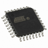
ATMEGA168-15AZ Atmel, ATMEGA168-15AZ Datasheet - Page 196

ATMEGA168-15AZ
Manufacturer Part Number
ATMEGA168-15AZ
Description
MCU AVR 16K FLASH 15MHZ 32-TQFP
Manufacturer
Atmel
Series
AVR® ATmegar
Datasheet
1.ATMEGA168-15AZ.pdf
(340 pages)
Specifications of ATMEGA168-15AZ
Package / Case
32-TQFP, 32-VQFP
Voltage - Supply (vcc/vdd)
2.7 V ~ 5.5 V
Operating Temperature
-40°C ~ 125°C
Speed
16MHz
Number Of I /o
23
Eeprom Size
512 x 8
Core Processor
AVR
Program Memory Type
FLASH
Ram Size
1K x 8
Program Memory Size
16KB (16K x 8)
Data Converters
A/D 8x10b
Oscillator Type
Internal
Peripherals
Brown-out Detect/Reset, POR, PWM, WDT
Connectivity
I²C, SPI, UART/USART
Core Size
8-Bit
Cpu Family
ATmega
Device Core
AVR
Device Core Size
8b
Frequency (max)
16MHz
Interface Type
2-Wire/USART/Serial
Total Internal Ram Size
1KB
# I/os (max)
23
Number Of Timers - General Purpose
3
Operating Supply Voltage (typ)
3.3/5V
Operating Supply Voltage (max)
5.5V
Operating Supply Voltage (min)
2.7V
On-chip Adc
8-chx10-bit
Instruction Set Architecture
RISC
Operating Temp Range
-40C to 125C
Operating Temperature Classification
Automotive
Mounting
Surface Mount
Pin Count
32
Package Type
TQFP
Lead Free Status / RoHS Status
Lead free / RoHS Compliant
Available stocks
Company
Part Number
Manufacturer
Quantity
Price
- Current page: 196 of 340
- Download datasheet (6Mb)
18.5
196
Data Transfer
ATmega48/88/168 Automotive
Using the USART in MSPI mode requires the Transmitter to be enabled, i.e. the TXENn bit in
the UCSRnB register is set to one. When the Transmitter is enabled, the normal port operation
of the TxDn pin is overridden and given the function as the Transmitter's serial output. Enabling
the receiver is optional and is done by setting the RXENn bit in the UCSRnB register to one.
When the receiver is enabled, the normal pin operation of the RxDn pin is overridden and given
the function as the Receiver's serial input. The XCKn will in both cases be used as the transfer
clock.
After initialization the USART is ready for doing data transfers. A data transfer is initiated by writ-
ing to the UDRn I/O location. This is the case for both sending and receiving data since the
transmitter controls the transfer clock. The data written to UDRn is moved from the transmit buf-
fer to the shift register when the shift register is ready to send a new frame.
Note:
The following code examples show a simple USART in MSPIM mode transfer function based on
polling of the Data Register Empty (UDREn) Flag and the Receive Complete (RXCn) Flag. The
USART has to be initialized before the function can be used. For the assembly code, the data to
be sent is assumed to be stored in Register R16 and the data received will be available in the
same register (R16) after the function returns.
The function simply waits for the transmit buffer to be empty by checking the UDREn Flag,
before loading it with new data to be transmitted. The function then waits for data to be present
in the receive buffer by checking the RXCn Flag, before reading the buffer and returning the
value.
To keep the input buffer in sync with the number of data bytes transmitted, the UDRn register must
be read once for each byte transmitted. The input buffer operation is identical to normal USART
mode, i.e. if an overflow occurs the character last received will be lost, not the first data in the buf-
fer. This means that if four bytes are transferred, byte 1 first, then byte 2, 3, and 4, and the UDRn
is not read before all transfers are completed, then byte 3 to be received will be lost, and not byte
1.
7530I–AVR–02/10
Related parts for ATMEGA168-15AZ
Image
Part Number
Description
Manufacturer
Datasheet
Request
R

Part Number:
Description:
Manufacturer:
Atmel Corporation
Datasheet:

Part Number:
Description:
Manufacturer:
Atmel Corporation
Datasheet:

Part Number:
Description:
Manufacturer:
ATMEL Corporation
Datasheet:

Part Number:
Description:
IC AVR MCU 16K 20MHZ 32TQFP
Manufacturer:
Atmel
Datasheet:

Part Number:
Description:
IC AVR MCU 16K 20MHZ 32-QFN
Manufacturer:
Atmel
Datasheet:

Part Number:
Description:
IC AVR MCU 16K 20MHZ 28DIP
Manufacturer:
Atmel
Datasheet:

Part Number:
Description:
MCU AVR 16K FLASH 15MHZ 32-QFN
Manufacturer:
Atmel
Datasheet:

Part Number:
Description:
IC AVR MCU 16K 20MHZ 32TQFP
Manufacturer:
Atmel
Datasheet:

Part Number:
Description:
MCU AVR 16KB FLASH 20MHZ 32QFN
Manufacturer:
Atmel
Datasheet:

Part Number:
Description:
MCU AVR 16KB FLASH 20MHZ 32TQFP
Manufacturer:
Atmel
Datasheet:

Part Number:
Description:
IC MCU AVR 16K FLASH 32-QFN
Manufacturer:
Atmel
Datasheet:


