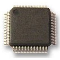
UPD78F0413GA-GAM-AX NEC, UPD78F0413GA-GAM-AX Datasheet - Page 368

UPD78F0413GA-GAM-AX
Manufacturer Part Number
UPD78F0413GA-GAM-AX
Description
8BIT UC, 32K FLASH, 1KB RAM, LCD
Manufacturer
NEC
Datasheet
1.UPD78F0413GA-GAM-AX.pdf
(562 pages)
Specifications of UPD78F0413GA-GAM-AX
Controller Family/series
UPD78F
No. Of I/o's
30
Ram Memory Size
1024Byte
Cpu Speed
10MHz
No. Of Timers
8
No. Of Pwm
RoHS Compliant
Core Size
8bit
Program Memory Size
32KB
Oscillator Type
External, Internal
Available stocks
Company
Part Number
Manufacturer
Quantity
Price
Company:
Part Number:
UPD78F0413GA-GAM-AX
Manufacturer:
ADI
Quantity:
882
Company:
Part Number:
UPD78F0413GA-GAM-AX
Manufacturer:
Renesas Electronics America
Quantity:
10 000
- Current page: 368 of 562
- Download datasheet (4Mb)
14.4.3 Dedicated baud rate generator
generates a serial clock for transmission/reception of UART6.
(1) Configuration of baud rate generator
368
The dedicated baud rate generator consists of a source clock selector and an 8-bit programmable counter, and
Separate 8-bit counters are provided for transmission and reception.
Base clock
The clock selected by bits 3 to 0 (TPS63 to TPS60) of clock selection register 6 (CKSR6) is supplied to
each module when bit 7 (POWER6) of asynchronous serial interface operation mode register 6 (ASIM6) is
1. This clock is called the base clock and its frequency is called f
when POWER6 = 0.
Transmission counter
This counter stops operation, cleared to 0, when bit 7 (POWER6) or bit 6 (TXE6) of asynchronous serial
interface operation mode register 6 (ASIM6) is 0.
It starts counting when POWER6 = 1 and TXE6 = 1.
The counter is cleared to 0 when the first data transmitted is written to transmit buffer register 6 (TXB6).
If data are continuously transmitted, the counter is cleared to 0 again when one frame of data has been
completely transmitted. If there is no data to be transmitted next, the counter is not cleared to 0 and continues
counting until POWER6 or TXE6 is cleared to 0.
Reception counter
This counter stops operation, cleared to 0, when bit 7 (POWER6) or bit 5 (RXE6) of asynchronous serial
interface operation mode register 6 (ASIM6) is 0.
It starts counting when the start bit has been detected.
The counter stops operation after one frame has been received, until the next start bit is detected.
CHAPTER 14 SERIAL INTERFACE UART6
User’s Manual U18698EJ1V0UD
XCLK6
. The base clock is fixed to low level
Related parts for UPD78F0413GA-GAM-AX
Image
Part Number
Description
Manufacturer
Datasheet
Request
R

Part Number:
Description:
16/8 bit single-chip microcomputer
Manufacturer:
NEC
Datasheet:

Part Number:
Description:
Dual audio power amp circuit
Manufacturer:
NEC
Datasheet:

Part Number:
Description:
Dual comparator
Manufacturer:
NEC
Datasheet:

Part Number:
Description:
MOS type composite field effect transistor
Manufacturer:
NEC
Datasheet:

Part Number:
Description:
50 V/100 mA FET array incorporating 2 N-ch MOSFETs
Manufacturer:
NEC
Datasheet:

Part Number:
Description:
6-pin small MM high-frequency double transistor
Manufacturer:
NEC
Datasheet:

Part Number:
Description:
6-pin small MM high-frequency double transistor
Manufacturer:
NEC
Datasheet:

Part Number:
Description:
6-pin small MM high-frequency double transistor
Manufacturer:
NEC
Datasheet:

Part Number:
Description:
6-pin small MM high-frequency double transistor
Manufacturer:
NEC
Datasheet:

Part Number:
Description:
Twin transistors equipped with different model chips(6P small MM)
Manufacturer:
NEC
Datasheet:

Part Number:
Description:
Bipolar analog integrated circuit
Manufacturer:
NEC
Datasheet:


