ATEVK1104 Atmel, ATEVK1104 Datasheet - Page 681
ATEVK1104
Manufacturer Part Number
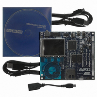
ATEVK1104
Description
KIT DEV/EVAL FOR AVR32 AT32UC3A
Manufacturer
Atmel
Series
AVR®32r
Type
MCUr
Datasheets
1.ATAVRONE-PROBECBL.pdf
(16 pages)
2.ATEVK1104.pdf
(826 pages)
3.ATEVK1104.pdf
(90 pages)
4.ATEVK1104.pdf
(6 pages)
5.ATEVK1104.pdf
(12 pages)
Specifications of ATEVK1104
Contents
Evaluation Board, Software and Documentation
Processor To Be Evaluated
AT32UC3A3
Data Bus Width
32 bit
Interface Type
USB, SPI, USART
Silicon Manufacturer
Atmel
Core Architecture
AVR
Core Sub-architecture
AVR UC3
Silicon Core Number
AT32UC3A3256
Silicon Family Name
AVR
Kit Contents
Board CD Docs
Rohs Compliant
Yes
For Use With/related Products
AT32UC3A3
Lead Free Status / RoHS Status
Lead free / RoHS Compliant
Available stocks
Company
Part Number
Manufacturer
Quantity
Price
Company:

Part Number:
ATEVK1104
Manufacturer:
Atmel
Quantity:
135


32.6.3
32.6.3.1
32.6.3.2
32.6.3.3
32058J–AVR32–04/11
PWM Controller Operations
Initialization
Changing the Duty Cycle or the Period
Source Clock Selection Criteria
Before enabling the output channel, this channel must have been configured by the software
application:
• Configuration of the clock generator if DIVA and DIVB are required
• Selection of the clock for each channel (CPRE field in the CMRx register)
• Configuration of the waveform alignment for each channel (CALG field in the CMRx register)
• Configuration of the period for each channel (CPRD in the CPRDx register). Writing in CPRDx
• Configuration of the duty cycle for each channel (CDTY in the CDTYx register). Writing in
• Configuration of the output waveform polarity for each channel (CPOL in the CMRx register)
• Enable Interrupts (Writing CHIDx in the IER register)
• Enable the PWM channel (Writing CHIDx in the ENA register)
It is possible to synchronize different channels by enabling them at the same time by means of
writing simultaneously several CHIDx bits in the ENA register.
In such a situation, all channels may have the same clock selector configuration and the same
period specified.
The large number of source clocks can make selection difficult. The relationship between the
value in the Period Register (CPRDx) and the Duty Cycle Register (CDTYx) can help the user in
choosing. The event number written in the Period Register gives the PWM accuracy. The Duty
Cycle quantum cannot be lower than 1/CPRDx value. The higher the value of CPRDx, the
greater the PWM accuracy.
For example, if the user sets 15 (in decimal) in CPRDx, the user is able to set a value between 1
up to 14 in CDTYx Register. The resulting duty cycle quantum cannot be lower than 1/15 of the
PWM period.
It is possible to modulate the output waveform duty cycle or period.
To prevent unexpected output waveform, the user must use the update register (PWM_CUPDx)
to change waveform parameters while the channel is still enabled. The user can write a new
period value or duty cycle value in the update register (CUPDx). This register holds the new
value until the end of the current cycle and updates the value for the next cycle. Depending on
the CPD field in the CMRx register, CUPDx either updates CPRDx or CDTYx. Note that even if
the update register is used, the period must not be smaller than the duty cycle.
Register is possible while the channel is disabled. After validation of the channel, the user must
use CUPDx Register to update CPRDx as explained below.
CDTYx Register is possible while the channel is disabled. After validation of the channel, the
user must use CUPDx Register to update CDTYx as explained below.
AT32UC3A
681
Related parts for ATEVK1104
Image
Part Number
Description
Manufacturer
Datasheet
Request
R

Part Number:
Description:
DEV KIT FOR AVR/AVR32
Manufacturer:
Atmel
Datasheet:

Part Number:
Description:
INTERVAL AND WIPE/WASH WIPER CONTROL IC WITH DELAY
Manufacturer:
ATMEL Corporation
Datasheet:
Part Number:
Description:
Low-Voltage Voice-Switched IC for Hands-Free Operation
Manufacturer:
ATMEL Corporation
Datasheet:
Part Number:
Description:
MONOLITHIC INTEGRATED FEATUREPHONE CIRCUIT
Manufacturer:
ATMEL Corporation
Datasheet:
Part Number:
Description:
AM-FM Receiver IC U4255BM-M
Manufacturer:
ATMEL Corporation
Datasheet:
Part Number:
Description:
Monolithic Integrated Feature Phone Circuit
Manufacturer:
ATMEL Corporation
Datasheet:
Part Number:
Description:
Multistandard Video-IF and Quasi Parallel Sound Processing
Manufacturer:
ATMEL Corporation
Datasheet:
Part Number:
Description:
High-performance EE PLD
Manufacturer:
ATMEL Corporation
Datasheet:
Part Number:
Description:
8-bit Flash Microcontroller
Manufacturer:
ATMEL Corporation
Datasheet:
Part Number:
Description:
2-Wire Serial EEPROM
Manufacturer:
ATMEL Corporation
Datasheet: